
Toepler plus

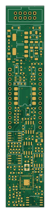
About the Toepler plus PCB
Toepler plus is an open source RP2040/RP2350 PCB design by niektb, published on GitHub under the CC-BY-SA-4.0 license. It is a 2-layer board measuring 20 × 106 mm, with 112 components from 37 distinct parts.
Its main chip is the RP2040, from the RP2040/RP2350 family. Other key parts include the TL072CD, LM4040DBZ-10, W25Q128JVSIQ, MCP6002-I-SN and AMS1117-5.0. By type, the board carries 45 resistors, 39 capacitors, 12 ICs, 9 diodes, 3 connectors and 1 transistor.
It belongs with the audio designs in this gallery.
From the project
Published Modules of the Sluisbrinkie project
In case you bought a PCB (with assembled SMD components) and panel from me, there are a number of things you need to finish the build: - 5x Thonkiconn mono jacks - 1x Thonkiconn stereo jack - 3x pushbuttons with at least 13mm shaft - 2x 10kOhm Type B potentiometer (Bourns PVT09 series are used in my builds) - 2x potentiometer knobs (see note below) - 2x WS2812B RGB LEDs - 1x USB-C UJ20-C-V-C-2-SMT-TR - 1x 2x5 pinheader (for eurorack power supply) - 2x 13p pinheader single row (for connecting back PCB to front PCB) - 2x 13p pinsocket single row (for connecting back PCB to front PCB) - M2.5…
Main components on the Toepler plus
Toepler plus bill of materials (BOM)
112 components, 37 distinct parts — part numbers from the project's BOM.
| Qty | Part | Footprint | Refs |
|---|---|---|---|
| 2 | TL072CD | SOIC-8_3.9x4.9mm_P1.27mm | IC1, IC2 |
| 1 | LM4040DBZ-10 | SOT-23 | U1 |
| 1 | RP2040 | QFN40P700X700X90-57N | U2 |
| 1 | W25Q128JVSIQ | SOIC127P790X216-8N | U3 |
| 1 | TL072CD | SO-8_3.9x4.9mm_P1.27mm | U4 |
| 2 | MCP6002-I-SN | SO-8_3.9x4.9mm_P1.27mm | U5, U8 |
| 1 | AMS1117-5.0 | SOT-223-3_TabPin2 | U6 |
| 1 | AMS1117-3.3 | SOT-223-3_TabPin2 | U7 |
| 1 | SN74LV1T125DBV | SOT-23-5 | U9 |
| 1 | USBLC6-2SC6SOT23-6 | SOT95P280X145-6N | U$3 |
| 1 | X322512MSB4SI | NX3225 | Q1 |
| 1 | CONN_02X05_ODD_EVEN Conn_02x05_Odd_Even | IDC-Header_2x05_P2.54mm_Vertical | J1 |
| 2 | CONN_01X13 Conn_01x13 | PinHeader_1x13_P2.54mm_Vertical | J3, J4 |
| 1 | 6N137S1(TA) | SMDIP-8_W9.53mm | OC1 |
| 1 | C2290 | CHIP-LED0603 | LED0 |
| 9 | B140HW-7 B5819W SL Diodes Incorporated | D_SOD-123 | D1, D2, D3, D4, D5, D6, D7, D8 +1 |
| 1 | BLM15H | L_0402_1005Metric | L2 |
| 7 | CL31A226KAHNNNE | C_1206_3216Metric | C1, C12, C13, C17, C18, C23, C38 |
| 5 | 100N 100n | C_0603_1608Metric | C2, C3, C5, C36, C37 |
| 1 | 1n | C_0603_1608Metric | C4 |
Show 17 more
| Qty | Part | Footprint | Refs |
|---|---|---|---|
| 14 | 100NF 100nF | C_0603_1608Metric | C6, C14, C15, C19, C26, C28, C32, C41 +6 |
| 2 | 150PF 150pf | C_0603_1608Metric | C7, C8 |
| 2 | 4.7NF 4.7nF | C_0603_1608Metric | C10, C11 |
| 2 | 10N 10n | C_0603_1608Metric | C16, C27 |
| 4 | 4U7F 4u7F | C_0603_1608Metric | C20, C21, C22, C29 |
| 2 | 33PF 33pF | C_0603_1608Metric | C24, C25 |
| 2 | 5K1 5k1 | R_0603_1608Metric | R1, R2 |
| 17 | 100K 100k | R_0603_1608Metric | R3, R4, R10, R11, R12, R14, R15, R17 +9 |
| 1 | 200K 200k | R_0603_1608Metric | R8 |
| 5 | 33K 33k | R_0603_1608Metric | R13, R23, R24, R30, R40 |
| 4 | 3.9k 0.1% | R_0603_1608Metric | R26, R27, R28, R29 |
| 2 | 27R | R_0603_1608Metric | R31, R32 |
| 4 | 10K 10k | R_0603_1608Metric | R33, R37, R39, R53 |
| 3 | 330R | R_0603_1608Metric | R34, R43, R46 |
| 5 | 1k | R_0603_1608Metric | R35, R36, R42, R50, R51 |
| 1 | 220 | R_0603_1608Metric | R38 |
| 1 | 2k | R_0603_1608Metric | R52 |
Toepler plus design files
The KiCad project lives in the niektb/sluisbrinkie-eurorack-published repository on GitHub; these links point at the commit this page was built from.
Toepler plus: common questions
What microcontroller does the Toepler plus use?
The Toepler plus is built around the RP2040, from the RP2040/RP2350 family.
How big is the Toepler plus PCB?
The Toepler plus measures 20 × 106 mm, has 2 copper layers and is 1.6 mm thick.
How many components are on the Toepler plus?
112 components, from 37 distinct parts, with part numbers taken from the project's own BOM. The full bill of materials is listed on this page.
Where can I download the Toepler plus design files?
From the niektb/sluisbrinkie-eurorack-published repository on GitHub, which has the KiCad layout, the schematic and the BOM; the links under Design files point to each one.
Can I use the Toepler plus design in my own project?
Yes, under the terms of its CC-BY-SA-4.0 license, which niektb chose for the repository.
Can I test firmware for the Toepler plus without the hardware?
Yes. HardLabs builds a simulation of the board from its netlist and BOM, so you can run and debug RP2040/RP2350 firmware against it before you order a PCB.
More boards in sluisbrinkie-eurorack-published
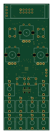 RP2040/RP2350
MMM main
40 × 110 mm145 parts4LCC-BY-SA-4.034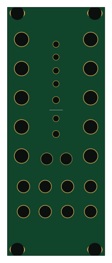
!!UNTESTED!!
50.5 × 128.5 mm124 parts2LCC-BY-SA-4.034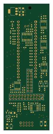
Andes
40 × 110 mm109 parts2LCC-BY-SA-4.034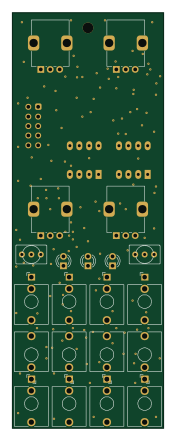
Herford
40 × 110 mm109 parts2LCC-BY-SA-4.034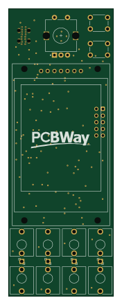 RP2040/RP2350
PI SCOPE
40 × 110 mm97 parts2LCC-BY-SA-4.034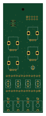
Fv1 module
40 × 110 mm80 parts2LCC-BY-SA-4.034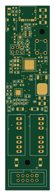 AVR/Arduino
USB C PD PSU
24 × 100 mm65 parts2LCC-BY-SA-4.034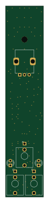
Divn
20 × 100 mm60 parts2LCC-BY-SA-4.034
Similar boards
 RP2040/RP2350
OSO-BOOK-C1
joeycastillo
85 × 115 mm29 parts2LCC-BY-SA-4.08.1k RP2040/RP2350
Corne cherry
foostan
277.2 × 107.5 mm164 parts2LCC-BY-4.07.7k RP2040/RP2350
Corne chocolate
277.2 × 107.5 mm164 parts2LCC-BY-4.07.7k RP2040/RP2350
Jitx design
gusmanb
55.5 × 65 mm26 parts4LGPL-3.05.0k RP2040/RP2350
LogicAnalyzer
57 × 55.2 mm6 parts2LGPL-3.05.0k RP2040/RP2350
Main
google
98 × 71 mm102 parts2LApache-2.02.9k