
Multistepper

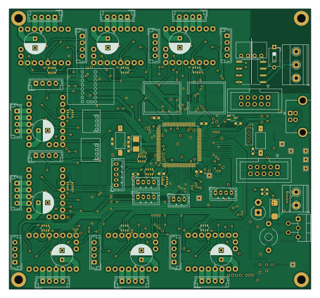
About the Multistepper PCB
Multistepper is an open source STM32 PCB design by eddyem, published on GitHub. It is a 4-layer board measuring 113.5 × 105.5 mm, with 234 components from 93 distinct parts.
Its main chip is the BME280, from the STM32 family. Other key parts include the STM32F303CBT6, ISO1050DUB, 74HC4051, PC844 and LM2576HVS-5. By type, the board carries 71 jumpers, 48 resistors, 29 capacitors, 27 connectors, 27 diodes and 8 ICs.
It belongs with the sensors designs in this gallery.
From the project
Code samples and ready projects based on bare-metal STM32
Management of 8 independend steppers ====================================
Eighth stepper could be changed to 8 dependent multiplexed. Based on STM32F303VDT6.
(all GPIO outs are push-pull if not mentioned another)
Each motor have next control signals: EN - enable driver, DIR - rotation direction, STEP - microstepping clock signal, L0 - zero end-switch, L1 - max end-switch (or Cable Select for SPI-based TMC).
Main components on the Multistepper
Multistepper bill of materials (BOM)
234 components, 93 distinct parts — part numbers from the project's BOM.
| Qty | Part | Footprint | Refs |
|---|---|---|---|
| 1 | BME280 STM32F303VDTx | LQFP-100_14x14mm_P0.5mm | U1 |
| 1 | STM32F303CBT6 ISO1050DUB | SOP-8_6.62x9.15mm_P2.54mm | U2 |
| 1 | ISO1050DUB USBLC6-2SC6 | SOT-23-6 | U3 |
| 1 | 74HC4051 LM4050A(b)EX3-3.3 | SOT-323_SC-70_Handsoldering | U4 |
| 1 | 74HC4051 LM2576-5.0 Texas Instruments | TO-220-5_P3.4x3.7mm_StaggerEven_Lead3.8mm_Vertical | U5 |
| 1 | PC844 LM1117-3.3 | SOT-223-3_TabPin2 | U6 |
| 1 | PC844 74HC4051 | SOIC-16_3.9x9.9mm_P1.27mm | U7 |
| 1 | LM2576HVS-5 LM1117-3.3 | SOT-223-3_TabPin2 | U8 |
| 1 | B0505S-1W B0505S | B0x0xS | Q1 |
| 1 | B0509S-1W IRF9310 | SO-8_3.9x4.9mm_P1.27mm | Q2 |
| 1 | SI2308 DTA114Y | SOT-323_SC-70_Handsoldering | Q3 |
| 1 | 8MHZ NX5032GA-8MHz | Crystal_SMD_5032-2Pin_5.0x3.2mm | Y1 |
| 1 | Prog | PinSocket_1x06_P1.27mm_Vertical | J1 |
| 1 | Buttons/I2C | IDC-Header_2x05_P2.54mm_Vertical | J2 |
| 1 | Screen | IDC-Header_2x05_P2.54mm_Vertical | J3 |
| 1 | ADC2 | JST_PH_B4B-PH-K_1x04_P2.00mm_Vertical | J4 |
| 1 | ADC1 | JST_PH_B4B-PH-K_1x04_P2.00mm_Vertical | J5 |
| 1 | MOT_MUL | JST_PH_B5B-PH-K_1x05_P2.00mm_Vertical | J6 |
| 1 | GPIO | JST_PH_B4B-PH-K_1x04_P2.00mm_Vertical | J7 |
| 1 | USB_B | USB_B_OST_USB-B1HSxx_Horizontal | J8 |
Show 73 more
| Qty | Part | Footprint | Refs |
|---|---|---|---|
| 1 | RS-485 Screw_Terminal_01x03 | TerminalBlock_Phoenix_MKDS-1,5-3_1x03_P5.00mm_Horizontal | J9 |
| 1 | Screw_Terminal_01x02 | TerminalBlock_Phoenix_MKDS-1,5-2_1x02_P5.00mm_Horizontal | J10 |
| 8 | LimS | JST_EH_B4B-EH-A_1x04_P2.50mm_Vertical | J11, J14, J16, J18, J20, J22, J24, J26 |
| 8 | Stepper | JST_EH_B4B-EH-A_1x04_P2.50mm_Vertical | J12, J15, J17, J19, J21, J23, J25, J27 |
| 1 | UART | JST_PH_B3B-PH-K_1x03_P2.00mm_Vertical | J13 |
| 1 | SOLDERJUMPER_2_OPEN CAN | SolderJumper-2_P1.3mm_Open_TrianglePad1.0x1.5mm | JP1 |
| 1 | SOLDERJUMPER_2_OPEN USB5V | SolderJumper-2_P1.3mm_Open_TrianglePad1.0x1.5mm | JP2 |
| 1 | SOLDERJUMPER_2_OPEN MCU | SolderJumper-2_P1.3mm_Open_TrianglePad1.0x1.5mm | JP3 |
| 1 | SOLDERJUMPER_2_OPEN 3V3ADC | SolderJumper-2_P1.3mm_Open_TrianglePad1.0x1.5mm | JP4 |
| 1 | SOLDERJUMPER_2_OPEN 3V3 | SolderJumper-2_P1.3mm_Open_TrianglePad1.0x1.5mm | JP5 |
| 1 | SOLDERJUMPER_2_OPEN Vdrive | SolderJumper-2_P1.3mm_Open_TrianglePad1.0x1.5mm | JP6 |
| 1 | SOLDERJUMPER_2_OPEN Vio | SolderJumper-2_P1.3mm_Open_TrianglePad1.0x1.5mm | JP7 |
| 38 | SolderJumper_3_Open | SolderJumper-3_P2.0mm_Open_TrianglePad1.0x1.5mm | JP8, JP9, JP12, JP16, JP17, JP18, JP19, JP20 +30 |
| 2 | SOLDERJUMPER_2_OPEN SolderJumper_3_Open | SolderJumper-3_P2.0mm_Open_TrianglePad1.0x1.5mm | JP10, JP11 |
| 24 | SolderJumper_2_Bridged | SolderJumper-2_P1.3mm_Open_TrianglePad1.0x1.5mm | JP13, JP14, JP15, JP21, JP22, JP23, JP29, JP30 +16 |
| 1 | SW_DIP_X01 Reset | SW_SPST_FSMSM | SW1 |
| 1 | SW_DIP_X04 Boot | SW_SPST_FSMSM | SW2 |
| 1 | SW_DIP_x01 | SW_DIP_SPSTx01_Slide_6.7x4.1mm_W7.62mm_P2.54mm_LowProfile | SW3 |
| 1 | 5Vusb | TestPoint_THTPad_1.5x1.5mm_Drill0.7mm | TP1 |
| 1 | Vin | TestPoint_THTPad_1.5x1.5mm_Drill0.7mm | TP2 |
| 1 | Gnd | TestPoint_THTPad_1.5x1.5mm_Drill0.7mm | TP3 |
| 1 | 24V 5Vext | TestPoint_THTPad_1.5x1.5mm_Drill0.7mm | TP4 |
| 1 | 3.3V | TestPoint_THTPad_1.5x1.5mm_Drill0.7mm | TP5 |
| 1 | 4.6V 3V3ADC | TestPoint_THTPad_1.5x1.5mm_Drill0.7mm | TP6 |
| 1 | 3.3V 5V | TestPoint_THTPad_1.5x1.5mm_Drill0.7mm | TP7 |
| 1 | Vio | TestPoint_THTPad_1.5x1.5mm_Drill0.7mm | TP8 |
| 8 | stepper_module | stepper_module | XX1, XX2, XX3, XX4, XX5, XX6, XX7, XX8 |
| 8 | SP0505BAHT | SOT-23-6 | D1, D2, D3, D4, D5, D6, D7, D8 |
| 1 | SMBJ30A SS14 | D_SOD-323_HandSoldering | D9 |
| 1 | PESD1CAN SS14 | D_SOD-323_HandSoldering | D10 |
| 1 | 1N5822 SS14 | D_SOD-323_HandSoldering | D11 |
| 2 | B340A SS14 | D_SOD-323_HandSoldering | D12, D13 |
| 3 | SM712_SOT23 SS14 | D_SOD-323_HandSoldering | D14, D15, D17 |
| 1 | SS14 | D_SOD-323_HandSoldering | D16 |
| 5 | SS14 | D_SOD-323_HandSoldering | D18, D19, D20, D21, D23 |
| 2 | MBRS130L | D_SMB_Handsoldering | D22, D27 |
| 1 | PESD1CAN | SOT-23 | D24 |
| 1 | MM3Z7V5 | D_0805_2012Metric_Pad1.15x1.40mm_HandSolder | D25 |
| 1 | 1N5822 | D_DO-201_P3.81mm_Vertical_AnodeUp | D26 |
| 1 | 100U 100u | L_Toroid_Horizontal_D6.5mm_P10.00mm_Diameter7-5mm_Amidon-T25 | L1 |
| 2 | 0.1 6 | C_0603_1608Metric_Pad1.08x0.95mm_HandSolder | C1, C4 |
| 5 | 0.1 | C_0603_1608Metric_Pad1.08x0.95mm_HandSolder | C2, C6, C7, C8, C27 |
| 6 | 0.1 | C_0603_1608Metric_Pad1.08x0.95mm_HandSolder | C3, C5, C9, C13, C15, C18 |
| 2 | 1u | C_0603_1608Metric_Pad1.08x0.95mm_HandSolder | C10, C12 |
| 1 | 0.1 1u | C_0603_1608Metric_Pad1.08x0.95mm_HandSolder | C11 |
| 1 | 47u 35V | CP_EIA-6032-28_Kemet-C_Pad2.25x2.35mm_HandSolder | C14 |
| 1 | 47u 6V | CP_EIA-3216-18_Kemet-A_Pad1.58x1.35mm_HandSolder | C16 |
| 1 | 47u 10V | CP_EIA-6032-28_Kemet-C_Pad2.25x2.35mm_HandSolder | C17 |
| 7 | 100u 35V | CP_Radial_D8.0mm_P3.50mm | C19, C20, C21, C22, C23, C24, C25 |
| 1 | 0.1 100u 35V | CP_Radial_D8.0mm_P3.50mm | C26 |
| 1 | 0.1 47u 6V | CP_EIA-3216-18_Kemet-A_Pad1.58x1.35mm_HandSolder | C28 |
| 1 | SE-5R5-D105VYV3C 0.1 | C_0603_1608Metric_Pad1.08x0.95mm_HandSolder | C29 |
| 1 | 10K 10k | R_0603_1608Metric_Pad0.98x0.95mm_HandSolder | R1 |
| 1 | 4K7 22 | R_0603_1608Metric_Pad0.98x0.95mm_HandSolder | R2 |
| 2 | 330 22 | R_0603_1608Metric_Pad0.98x0.95mm_HandSolder | R3, R9 |
| 1 | 330 7.5 | R_0603_1608Metric_Pad0.98x0.95mm_HandSolder | R4 |
| 1 | 330 5.1 | R_0603_1608Metric_Pad0.98x0.95mm_HandSolder | R5 |
| 3 | 330 | R_0603_1608Metric_Pad0.98x0.95mm_HandSolder | R6, R7, R8 |
| 1 | 330 91k | R_0603_1608Metric_Pad0.98x0.95mm_HandSolder | R10 |
| 1 | 330 10k | R_0603_1608Metric_Pad0.98x0.95mm_HandSolder | R11 |
| 1 | 4K7 47k | R_0603_1608Metric_Pad0.98x0.95mm_HandSolder | R12 |
| 1 | 3K3 47k | R_0603_1608Metric_Pad0.98x0.95mm_HandSolder | R13 |
| 2 | 3K3 330 | R_0603_1608Metric_Pad0.98x0.95mm_HandSolder | R14, R15 |
| 2 | 3K3 22 | R_0603_1608Metric_Pad0.98x0.95mm_HandSolder | R16, R17 |
| 1 | 3K3 120 | R_1210_3225Metric_Pad1.30x2.65mm_HandSolder | R18 |
| 2 | 3K3 4k7 | R_0603_1608Metric_Pad0.98x0.95mm_HandSolder | R19, R20 |
| 6 | 560 100 | R_0603_1608Metric_Pad0.98x0.95mm_HandSolder | R21, R22, R26, R27, R28, R29 |
| 1 | 120 100 | R_0603_1608Metric_Pad0.98x0.95mm_HandSolder | R23 |
| 2 | 560 22 | R_0603_1608Metric_Pad0.98x0.95mm_HandSolder | R24, R25 |
| 1 | 1K5 100 | R_0603_1608Metric_Pad0.98x0.95mm_HandSolder | R30 |
| 2 | 100 | R_0603_1608Metric_Pad0.98x0.95mm_HandSolder | R31, R32 |
| 1 | 10M 1k5 | R_0603_1608Metric_Pad0.98x0.95mm_HandSolder | R33 |
| 15 | 330 | R_Array_Convex_4x0603 | RN1, RN2, RN3, RN4, RN5, RN6, RN7, RN8 +7 |
Multistepper design files
The KiCad project lives in the eddyem/stm32samples repository on GitHub; these links point at the commit this page was built from.
Multistepper: common questions
What microcontroller does the Multistepper use?
The Multistepper is built around the BME280, from the STM32 family.
How big is the Multistepper PCB?
The Multistepper measures 113.5 × 105.5 mm, has 4 copper layers and is 4.69 mm thick.
How many components are on the Multistepper?
234 components, from 93 distinct parts, with part numbers taken from the project's own BOM. The full bill of materials is listed on this page.
Where can I download the Multistepper design files?
From the eddyem/stm32samples repository on GitHub, which has the KiCad layout, the schematic and the BOM; the links under Design files point to each one.
Can I use the Multistepper design in my own project?
The repository has no license, so all rights stay with eddyem. Use it as a reference, and ask the author before reusing the design.
Can I test firmware for the Multistepper without the hardware?
Yes. HardLabs builds a simulation of the board from its netlist and BOM, so you can run and debug STM32 firmware against it before you order a PCB.
More boards in stm32samples
- schematic only · 234 partsSTM32
Fx3u 24mr
234 parts2LNo license208 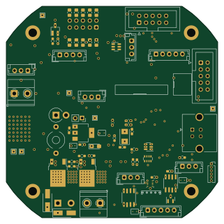 STM32
Nitrogen
80 × 80 mm136 parts4LNo license208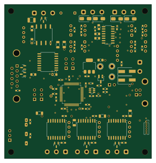 STM32
Many485
80 × 84 mm107 parts2LNo license208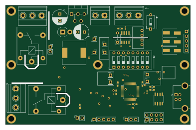 STM32
Stm32
98 × 63.5 mm98 parts2LNo license208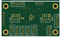 STM32
Mainboard
58 × 35 mm86 parts2LNo license208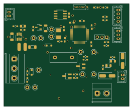 STM32
Windshield
66 × 54 mm86 parts2LNo license208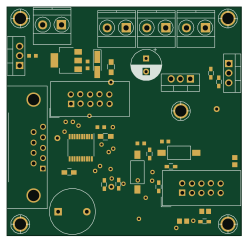 STM32
Chiller control
62 × 60.5 mm69 parts2LNo license208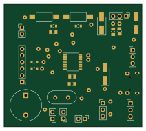 STM32
Servo control
53 × 47 mm59 parts2LNo license208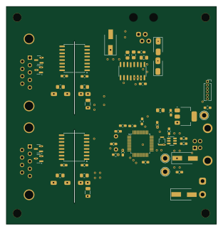 STM32
Encoder
78 × 81 mm53 parts2LNo license208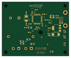 STM32
Shutter
61 × 49.5 mm40 parts2LNo license208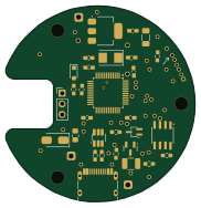 STM32
Hall
45.3 × 46.9 mm34 parts2LNo license208
Similar boards
 STM32
LumenPnP Motherboard
opulo-inc
149 × 95 mm296 parts4LCC-BY-SA-4.03.7k STM32
Base
google
52.3 × 52.3 mm36 parts2LApache-2.02.9k STM32
Main panel
234 × 84 mm26 parts4LApache-2.02.9k STM32
Type a
150 × 30 mm14 parts2LApache-2.02.9k STM32
Type g
169 × 30 mm24 parts2LApache-2.02.9k STM32
Type c
188 × 30 mm17 parts2LApache-2.02.9k