
IOT DEV BOARD

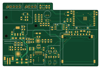
About the IOT DEV BOARD
IOT DEV BOARD is an open source ESP32 PCB design by landjas09, published on GitHub. It is a 4-layer board measuring 81.2 × 54.7 mm, with 81 components from 41 distinct parts.
Its main chip is the ESP32-C3-WROOM-02-H4, from the ESP32 family. Other key parts include the MCP73871-2CAI_ML, CP2102N-AXX-XQFN20, W25Q32JVSSIQ, USBLC6-2SC6 and BME280. By type, the board carries 31 resistors, 26 capacitors, 7 ICs, 6 LEDs, 5 connectors and 3 transistors.
It belongs with the power & battery, iot & wireless and dev boards & breakouts designs in this gallery.
From the project
Custom ESP32-C3 Secure-Ready Battery-Powered Edge Logger with environmental, light and acoustic sensing, local storage, DS3231 RTC, BQ27441 fuel gauging, SE050E2 secure element and TPS63802 buck-boost power. Designed in KiCad 10 with a custom Zephyr RTOS board port.
A custom-designed IoT development board built around the ESP32-C3-WROOM-02, featuring integrated LiPo battery charging, environmental sensing, ambient light sensing, audio capture, on-board storage (flash + SD card), and a USB-C interface with full USB-to-UART programming support. Designed end-to-end in KiCad 10, from schematic capture through PCB layout and routing.
Main components on the IOT DEV BOARD
IOT DEV BOARD bill of materials (BOM)
81 components, 41 distinct parts — part numbers from the project's BOM.
| Qty | Part | Footprint | Refs |
|---|---|---|---|
| 1 | MCP73871-2CAI_ML Microchip Corp. | QFN50P400X400X100-21N | U1 |
| 1 | CP2102N-AXX-XQFN20 CP2102N-Axx-xQFN20 | SiliconLabs_QFN-20-1EP_3x3mm_P0.5mm_EP1.8x1.8mm | U2 |
| 1 | ESP32-C3-WROOM-02-H4 | MODULE_ESP32-C3-WROOM-02-H4 | U3 |
| 1 | W25Q32JVSSIQ | SOIC127P790X216-8N | U4 |
| 1 | USBLC6-2SC6 | SOT-23-6 | U5 |
| 1 | BME280 | PSON65P250X250X100-8N | U6 |
| 1 | MAX4466EXK | SOT65P210X110-5N | U7 |
| 1 | TEMT6000X01 VISHAY | TRANS_TEMT6000X01 | Q1 |
| 2 | BC817 | SOT-23 | Q2, Q3 |
| 1 | SS-52400-002 BelFuse | BELFUSE_SS-52400-002 | J1 |
| 1 | B2B-PH-SM4-TB JST | JST_B2B-PH-SM4-TB | J2 |
| 1 | GSD090012SEU Amphenol | AMPHENOL_GSD090012SEU | J3 |
| 1 | CONN_01X04_PIN Conn_01x04_Pin | PinHeader_1x04_P2.54mm_Vertical | J4 |
| 1 | CONN_01X05_PIN Conn_01x05_Pin | PinHeader_1x05_P2.54mm_Vertical | J5 |
| 1 | 0ZCH0110AF2E | FUSC3226X100N | F1 |
| 1 | CMC-5042PF-AC CUI INC | CUI_CMC-5042PF-AC | MK1 |
| 1 | LM1117MPX-3.3_NOPB Texas Instruments | VREG_LM1117MPX-3.3 | VR1 |
| 3 | LTST-C170KRKT | LEDC2012X120N | LED1, LED4, LED5 |
| 2 | LTST-C170GKT | LEDC2012X120N | LED2, LED6 |
| 1 | LTST-C170TBKT | LEDC2012X120N | LED3 |
Show 21 more
| Qty | Part | Footprint | Refs |
|---|---|---|---|
| 4 | 10U 10u | T491A | C1, C5, C7, C15 |
| 3 | 4.7U 4.7u | T491A | C2, C3, C10 |
| 12 | 0.1U 0.1u | C_0805_2012Metric | C4, C6, C8, C9, C11, C12, C14, C16 +4 |
| 1 | 1OU 1Ou | T491A | C13 |
| 1 | 100P 100p | C_0805_2012Metric | C17 |
| 1 | 1u | C_0805_2012Metric | C18 |
| 1 | 0.01U 0.01u | C_0805_2012Metric | C19 |
| 1 | 100N 100n | C_0805_2012Metric | C23 |
| 2 | 10N 10n | C_0805_2012Metric | C24, C25 |
| 1 | 1k | R_0805_2012Metric | R1 |
| 7 | 10K | R_0805_2012Metric | R2, R22, R27, R28, R29, R30, R31 |
| 2 | 5K1 | R_0805_2012Metric | R3, R4 |
| 3 | 2k | R_0805_2012Metric | R5, R25, R26 |
| 1 | 20K | R_0805_2012Metric | R6 |
| 6 | 470 | R_0805_2012Metric | R7, R8, R9, R10, R11, R12 |
| 1 | 22K1 | R_0805_2012Metric | R13 |
| 1 | 47K5 | R_0805_2012Metric | R14 |
| 4 | 50 | R_0805_2012Metric | R15, R16, R17, R18 |
| 1 | 100K | R_0805_2012Metric | R19 |
| 2 | 4.7K R | R_0805_2012Metric | R20, R21 |
| 2 | 1M | R_0805_2012Metric | R23, R24 |
IOT DEV BOARD design files
The KiCad project lives in the landjas09/Secure-Ready-Battery-Powered-Edge-Logger repository on GitHub; these links point at the commit this page was built from.
IOT DEV BOARD: common questions
What microcontroller does the IOT DEV BOARD use?
The IOT DEV BOARD is built around the ESP32-C3-WROOM-02-H4, from the ESP32 family.
How big is the IOT DEV BOARD?
The IOT DEV BOARD measures 81.2 × 54.7 mm, has 4 copper layers and is 1.6 mm thick.
How many components are on the IOT DEV BOARD?
81 components, from 41 distinct parts, with part numbers taken from the project's own BOM. The full bill of materials is listed on this page.
Where can I download the IOT DEV BOARD design files?
From the landjas09/Secure-Ready-Battery-Powered-Edge-Logger repository on GitHub, which has the KiCad layout, the schematic and the BOM; the links under Design files point to each one.
Can I use the IOT DEV BOARD design in my own project?
The repository has no license, so all rights stay with landjas09. Use it as a reference, and ask the author before reusing the design.
Can I test firmware for the IOT DEV BOARD without the hardware?
Yes. HardLabs builds a simulation of the board from its netlist and BOM, so you can run and debug ESP32 firmware against it before you order a PCB.
More boards in Secure-Ready-Battery-Powered-Edge-Logger
Similar boards
 ESP32
OSO-BOOK-B1
joeycastillo
85 × 115 mm65 parts2LCC-BY-SA-4.08.1k ESP32
Powertrain
byrantech
64 × 45.4 mm171 parts4LMIT4.3k ESP32
Badge
atopile
56.3 × 39 mm239 parts4LMIT4.0k ESP32
Esp32 minimal
36.2 × 26.8 mm20 parts2LMIT4.0k ESP32
Racer
StuckAtPrototype
36 × 50.2 mm70 parts4LApache-2.03.8k ESP32
Controller
29 × 74 mm58 parts4LApache-2.03.8k