
Power Supply and Charge Circuit

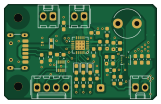
About the Power Supply and Charge Circuit PCB
Power Supply and Charge Circuit is an open source PCB design by owenpmorgan, published on GitHub. It is a 4-layer board measuring 40.1 × 25 mm, with 38 components from 28 distinct parts.
Other key parts include the SC3402, MCP73871, MAX17048 and TPS61235P. By type, the board carries 14 resistors, 9 capacitors, 6 connectors, 4 ICs, 3 diodes and 2 inductors.
It belongs with the rf & radio and power & battery designs in this gallery.
From the project
The motivation for this project is to create an electronic nose system using a low cost device. Essentially this means using an MCU rather than a small board computer (SBC) like MyRio or Raspberry Pi.
The motivation for this project is to create an electronic nose system using a low cost device. Essentially this means using an MCU rather than a small board computer (SBC) like MyRio or Raspberry Pi.
The benefits of using an SBC are that inference (that is, running the model on a new input to classify it) can stay in the realm in which models are built and a single script or two can take care of the whole model for both training and inference, via tools such as Matlab, Octave, LabView, TensorFlow etc.
Main components on the Power Supply and Charge Circuit
Power Supply and Charge Circuit bill of materials (BOM)
38 components, 28 distinct parts.
| Qty | Part | Footprint | Refs |
|---|---|---|---|
| 1 | SC3402 | SC3402 | U1 |
| 1 | MCP73871 | QFN-20-1EP_4x4mm_P0.5mm_EP2.5x2.5mm | U2 |
| 1 | MAX17048 | DFN8 MAX17048_9 | U3 |
| 1 | TPS61235P | VQFN9 TPS61235p | U4 |
| 1 | Therm | Molex_KK-254_AE-6410-02A_1x02_P2.54mm_Vertical | J1 |
| 1 | To Batteries | Molex_KK-254_AE-6410-02A_1x02_P2.54mm_Vertical | J2 |
| 1 | USB_C_Receptacle_PowerOnly_6P | USB_C_Receptacle_HRO_TYPE-C-31-M-17 | J3 |
| 1 | MCU | SolderWire-0.25sqmm_1x01_D0.65mm_OD2mm | J5 |
| 1 | To device | Molex_KK-254_AE-6410-02A_1x02_P2.54mm_Vertical | J6 |
| 1 | To MCU | Molex_KK-254_AE-6410-04A_1x04_P2.54mm_Vertical | J8 |
| 3 | LED | LED_0603_1608Metric_Pad1.05x0.95mm_HandSolder | D1, D2, D3 |
| 1 | FerriteBead | 74279261 Wurth Ferrite Bead | FB1 |
| 1 | 1u | L_Radial_D7.5mm_P5.00mm_Fastron_07P | L1 |
| 2 | 10u | C_0603_1608Metric_Pad1.08x0.95mm_HandSolder | C1, C4 |
| 1 | 100n | C_0603_1608Metric_Pad1.08x0.95mm_HandSolder | C2 |
| 1 | 1u | C_0603_1608Metric_Pad1.08x0.95mm_HandSolder | C3 |
| 1 | 10n | C_0603_1608Metric_Pad1.08x0.95mm_HandSolder | C5 |
| 3 | 22u | C_0603_1608Metric_Pad1.08x0.95mm_HandSolder | C6, C7, C8 |
| 1 | 4.7u | C_0603_1608Metric_Pad1.08x0.95mm_HandSolder | C9 |
| 1 | 100M | R_0603_1608Metric_Pad0.98x0.95mm_HandSolder | R1 |
Show 8 more
| Qty | Part | Footprint | Refs |
|---|---|---|---|
| 1 | 1k | R_0603_1608Metric_Pad0.98x0.95mm_HandSolder | R2 |
| 1 | 10k | R_0603_1608Metric_Pad0.98x0.95mm_HandSolder | R3 |
| 2 | 5.1k | R_0603_1608Metric_Pad0.98x0.95mm_HandSolder | R4, R5 |
| 3 | 470 | R_0603_1608Metric_Pad0.98x0.95mm_HandSolder | R6, R7, R8 |
| 3 | 1M | R_0603_1608Metric_Pad0.98x0.95mm_HandSolder | R9, R11, R13 |
| 1 | 41.2k | R_0603_1608Metric_Pad0.98x0.95mm_HandSolder | R10 |
| 1 | 0 | R_0603_1608Metric_Pad0.98x0.95mm_HandSolder | R12 |
| 1 | 332k | R_0603_1608Metric_Pad0.98x0.95mm_HandSolder | R14 |
Power Supply and Charge Circuit design files
The KiCad project lives in the owenpmorgan/STM_Based_Electronic_Nose_Platform repository on GitHub; these links point at the commit this page was built from.
Power Supply and Charge Circuit: common questions
How big is the Power Supply and Charge Circuit PCB?
The Power Supply and Charge Circuit measures 40.1 × 25 mm, has 4 copper layers and is 1.6 mm thick.
How many components are on the Power Supply and Charge Circuit?
38 components, from 28 distinct parts. The full bill of materials is listed on this page.
Where can I download the Power Supply and Charge Circuit design files?
From the owenpmorgan/STM_Based_Electronic_Nose_Platform repository on GitHub, which has the KiCad layout and the schematic; the links under Design files point to each one.
Can I use the Power Supply and Charge Circuit design in my own project?
The repository has no license, so all rights stay with owenpmorgan. Use it as a reference, and ask the author before reusing the design.
More boards in STM_Based_Electronic_Nose_Platform
![Top view of GIC Array[5]](https://hip.fly.dev/v1/gallery/thumb/owenpmorgan--stm-based-electronic-nose-platform--gic-array-5.svg)
GIC Array[5]
104.8 × 66.6 mm75 parts2LNo license0![Top view of GIC Array[5] complete not optimised](https://hip.fly.dev/v1/gallery/thumb/owenpmorgan--stm-based-electronic-nose-platform--gic-array-5-complete-not-optimised.svg)
GIC Array[5] complete not optimised
104.8 × 76.8 mm75 parts2LNo license0
Power Bus Board
31 × 41 mm20 parts2LNo license0
PWM Heater Control FULL with boost conv remake
48.9 × 47.1 mm20 parts2LNo license0
PWM to V PSU
75.2 × 45.7 mm18 parts2LNo license0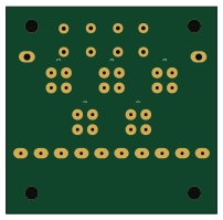
5 Piece Gas Sensor Mounting Board
50.5 × 49.5 mm17 parts2LNo license0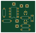
GIC Complete Circuit
31.8 × 29.2 mm14 parts2LNo license0
Debouncer
23.6 × 20 mm11 parts2LNo license0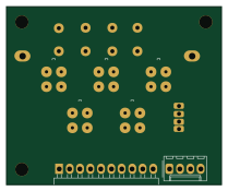
5 Piece Gas Sensor Mounting Board with TempHum sens
52.2 × 43.2 mm10 parts2LNo license0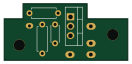
Heater Driver Simple
32.8 × 15 mm9 parts2LNo license0
Similar boards

Stack chan
stack-chan
50 × 50 mm33 parts2LApache-2.01.7k
Display Carrier
AxxAxx
35.6 × 58.2 mm5 parts2LGPL-3.01.7k
ControllerCurrentShuntAddOn
stuartpittaway
26 × 16.9 mm9 parts2LCC-BY-NC-4.01.1k
Module 16S PassiveBalanceAddOn
61 × 74 mm86 parts2LCC-BY-NC-4.01.1k
TemperaturePCB PANEL
116 × 75.5 mm178 parts2LCC-BY-NC-4.01.1k
ProgrammingAdapter
10.5 × 83 mm3 parts2LCC-BY-NC-4.01.1k