
Control and communication card

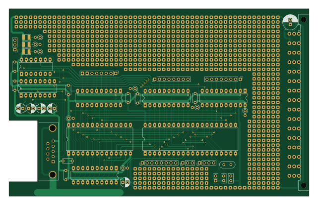
About the Control and communication card PCB
Control and communication card is an open source AVR/Arduino PCB design by pozsarzs, published on GitHub under the EUPL-1.2 license. It is a 2-layer board measuring 160 × 100.3 mm, with 45 components from 22 distinct parts.
Its main chip is the 87C51, from the AVR/Arduino family. Other key parts include the 27C64, 74LS573, 74LS08, MAX232 and 74LS245. By type, the board carries 16 capacitors, 8 ICs, 8 resistors, 7 connectors, 3 diodes and 2 jumpers.
It belongs with the retro computing designs in this gallery.
From the project
8-bit microcomputer built from commercially available and home-built components
The PEIX serves as an 8-slot external interface, designed to integrate legacy Klöckner-Moeller PS316 I/O modules with the Zacchaeus computer. Although the PS316 family has been obsolete since the mid-2000s, this circuit enables continued functionality by interfacing with the system's original analog and digital I/O modules.
The device is controlled by a circuit built with an 87C51 microcontroller. It is responsible for controlling the PLC modules and communicating with Zacchaeus via the RS-232 serial port.
Main components on the Control and communication card
Control and communication card bill of materials (BOM)
45 components, 22 distinct parts.
| Qty | Part | Footprint | Refs |
|---|---|---|---|
| 1 | 87C51 | DIP-40_W15.24mm_LongPads | U1 |
| 1 | 27C64 | DIP-28_W15.24mm_LongPads | U2 |
| 1 | 74LS573 | DIP-20_W7.62mm_LongPads | U3 |
| 1 | 74LS08 | DIP-14_W7.62mm_LongPads | U4 |
| 1 | MAX232 | DIP-16_W7.62mm_LongPads | U5 |
| 3 | 74LS245 | DIP-20_W7.62mm_LongPads | U6, U7, U8 |
| 1 | 11.0592 MHz | Crystal_HC52-6mm_Vertical | Y1 |
| 2 | Conn_01x08_Male | PinHeader_1x08_P2.54mm_Vertical | J1, J6 |
| 1 | Conn_01x03_Male | PinHeader_1x03_P2.54mm_Vertical | J2 |
| 1 | Conn_01x04_Male | PinHeader_1x04_P2.54mm_Vertical | J3 |
| 2 | locked | PinHeader_1x08_P2.54mm_Vertical | J4, J5 |
| 1 | locked | DIN41612_C_3x16_Male_Horizontal_THT | J8 |
| 1 | Ext ROM | PinHeader_1x02_P2.54mm_Vertical | JP1 |
| 1 | Jumper_3_Bridged12 | PinHeader_1x03_P2.54mm_Vertical | JP2 |
| 3 | LED | LED_PLCC-2_3.4x3.0mm_KA | D1, D2, D3 |
| 8 | 100n | C_Disc_D5.0mm_W2.5mm_P5.00mm | C1, C2, C5, C7, C8, C9, C10, C11 |
| 2 | 33 | C_Disc_D5.0mm_W2.5mm_P2.50mm | C3, C4 |
| 5 | 10u | CP_Radial_D5.0mm_P2.50mm | C6, C13, C14, C15, C16 |
| 1 | 100u | CP_Radial_D8.0mm_P2.50mm | C12 |
| 1 | 8.2k | R_Axial_DIN0207_L6.3mm_D2.5mm_P2.54mm_Vertical | R1 |
Show 2 more
| Qty | Part | Footprint | Refs |
|---|---|---|---|
| 4 | 1k | R_Axial_DIN0207_L6.3mm_D2.5mm_P2.54mm_Vertical | R2, R3, R7, R8 |
| 3 | 470 | R_Axial_DIN0207_L6.3mm_D2.5mm_P2.54mm_Vertical | R4, R5, R6 |
Control and communication card design files
The KiCad project lives in the pozsarzs/zacchaeus repository on GitHub; these links point at the commit this page was built from.
Control and communication card: common questions
What microcontroller does the Control and communication card use?
The Control and communication card is built around the 87C51, from the AVR/Arduino family.
How big is the Control and communication card PCB?
The Control and communication card measures 160 × 100.3 mm, has 2 copper layers and is 1.6 mm thick.
How many components are on the Control and communication card?
45 components, from 22 distinct parts. The full bill of materials is listed on this page.
Where can I download the Control and communication card design files?
From the pozsarzs/zacchaeus repository on GitHub, which has the KiCad layout and the schematic; the links under Design files point to each one.
Can I use the Control and communication card design in my own project?
Yes, under the terms of its EUPL-1.2 license, which pozsarzs chose for the repository.
Can I test firmware for the Control and communication card without the hardware?
Yes. HardLabs builds a simulation of the board from its netlist and BOM, so you can run and debug AVR/Arduino firmware against it before you order a PCB.
More boards in zacchaeus
PIOI I/O interface module
238.5 × 59.7 mm83 parts2LEUPL-1.20
PEMX - External memory box
150.5 × 219.1 mm79 parts2LEUPL-1.20
PMAN/SW - switch module
107.2 × 50.6 mm75 parts2LEUPL-1.20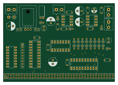
PCOX - COVOX module
102.6 × 72.4 mm56 parts2LEUPL-1.20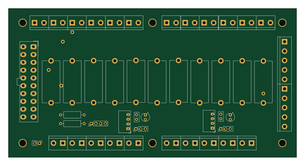
PPOW - Power distribution modul
154.9 × 80 mm48 parts2LEUPL-1.20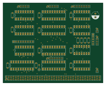
PMAN-IF Interface module
106.3 × 85.1 mm39 parts2LEUPL-1.20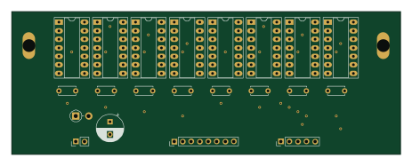
PMAN/DP - display module
115.6 × 42.6 mm21 parts2LEUPL-1.20
PSPK Speaker amplifier module
48.3 × 57.2 mm16 parts2LEUPL-1.20
Similar boards
 AVR/Arduino
Redox keyboard
mattdibi
162.2 × 126.5 mm77 parts2LMIT2.0k AVR/Arduino
ModuleV450
stuartpittaway
30 × 61.4 mm39 parts2LCC-BY-NC-4.01.1k AVR/Arduino
V4
30 × 50 mm38 parts2LCC-BY-NC-4.01.1k AVR/Arduino
Discipline
coseyfannitutti
304.9 × 122.8 mm170 parts2LCC-BY-NC-4.01.0k AVR/Arduino
Megadesk
gcormier
41.7 × 32.2 mm23 parts2LGPL-3.0818 AVR/Arduino
Easyduino Atmega Nano
Hanqaqa
43.4 × 18 mm30 parts4LCERN-OHL-P-2.0746