
SensorCard2

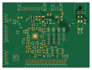
About the SensorCard2 PCB
SensorCard2 is an open source STM32 PCB design by roblesterjr04, published on GitHub under the MIT license. It is a 2-layer board measuring 80 × 60 mm, with 114 components from 57 distinct parts.
Its main chip is the STM32G0B1KBU6, from the STM32 family. Other key parts include the TJA1051T/3, MB85RC256V, PC817, AP2112K-3.3 and SN74LVC1T45. By type, the board carries 46 resistors, 23 capacitors, 16 jumpers, 11 diodes, 8 connectors and 6 ICs.
It belongs with the rf & radio designs in this gallery.
From the project
The DigiDash sensor pack on a slot card, rev A (SensorCard/) with the ATmega2560 + MCP2515 replaced by the GPS and radio cards' STM32G0B1KBU6 (Cortex-M0+, built-in FDCAN), on two layers. Same 80 × 60 mm card, same connectors in the same places, same CAN node (0x04, fixed), same f
The DigiDash sensor pack on a slot card, rev A (SensorCard/) with the ATmega2560 + MCP2515 replaced by the GPS and radio cards' STM32G0B1KBU6 (Cortex-M0+, built-in FDCAN), on two layers. Same 80 × 60 mm card, same connectors in the same places, same CAN node (0x04, fixed), same frames, same FRAM odometer. Started 2026-10-26 to take the one 100-pin, $13 chip and the CAN controller off the BOM and make the card a 2-layer board.
Main components on the SensorCard2
SensorCard2 bill of materials (BOM)
114 components, 57 distinct parts — part numbers from the project's BOM.
| Qty | Part | Footprint | Refs |
|---|---|---|---|
| 1 | STM32G0B1KBU6 | QFN-32-1EP_5x5mm_P0.5mm_EP3.45x3.45mm | U1 |
| 1 | TJA1051T/3 | SOIC-8_3.9x4.9mm_P1.27mm | U3 |
| 1 | MB85RC256V | SOIC-8_3.9x4.9mm_P1.27mm | U4 |
| 1 | PC817 | SMDIP-4_W7.62mm | U5 |
| 1 | AP2112K-3.3 | SOT-23-5 | U6 |
| 1 | SN74LVC1T45 | SOT-363_SC-70-6 | U7 |
| 1 | 8MHz | Oscillator_SMD_Abracon_ASE-4Pin_3.2x2.5mm | Y1 |
| 1 | DigiDash slot | PinHeader_2x15_P2.54mm_Horizontal | J1 |
| 1 | Senders | JST_PH_S12B-PH-K_1x12_P2.00mm_Horizontal | J2 |
| 1 | Speed | JST_PH_S4B-PH-K_1x04_P2.00mm_Horizontal | J3 |
| 1 | Tach | Molex_Micro-Fit_3.0_43650-0200_1x02_P3.00mm_Horizontal | J4 |
| 1 | RPM select | PinHeader_2x02_P2.54mm_Vertical | J5 |
| 1 | SWD | PinHeader_1x05_P2.54mm_Horizontal | J6 |
| 1 | Debug serial | PinHeader_1x06_P2.54mm_Horizontal | J7 |
| 1 | Sensor serial out | PinHeader_1x03_P2.54mm_Horizontal | J8 |
| 3 | PTC 0.1A | Fuse_1206_3216Metric | F1, F2, F3 |
| 1 | 5V / 12V | SolderJumper-3_P1.3mm_Bridged12_RoundedPad1.0x1.5mm | JP1 |
| 1 | FUEL PU / PD | SolderJumper-3_P1.3mm_Bridged12_RoundedPad1.0x1.5mm | JP2 |
| 1 | ETEMP PU / PD | SolderJumper-3_P1.3mm_Bridged12_RoundedPad1.0x1.5mm | JP3 |
| 1 | OILP PU / PD | SolderJumper-3_P1.3mm_Bridged12_RoundedPad1.0x1.5mm | JP4 |
Show 37 more
| Qty | Part | Footprint | Refs |
|---|---|---|---|
| 1 | AMB PU / PD | SolderJumper-3_P1.3mm_Bridged12_RoundedPad1.0x1.5mm | JP5 |
| 1 | FUEL 100 | SolderJumper-2_P1.3mm_Bridged_RoundedPad1.0x1.5mm | JP6 |
| 1 | FUEL 220 | SolderJumper-2_P1.3mm_Open_RoundedPad1.0x1.5mm | JP7 |
| 1 | FUEL 470 | SolderJumper-2_P1.3mm_Open_RoundedPad1.0x1.5mm | JP8 |
| 1 | ETEMP 220 | SolderJumper-2_P1.3mm_Open_RoundedPad1.0x1.5mm | JP9 |
| 1 | ETEMP 1k | SolderJumper-2_P1.3mm_Bridged_RoundedPad1.0x1.5mm | JP10 |
| 1 | ETEMP 10k | SolderJumper-2_P1.3mm_Open_RoundedPad1.0x1.5mm | JP11 |
| 1 | OILP 220 | SolderJumper-2_P1.3mm_Bridged_RoundedPad1.0x1.5mm | JP12 |
| 1 | OILP 1k | SolderJumper-2_P1.3mm_Open_RoundedPad1.0x1.5mm | JP13 |
| 1 | OILP 100k | SolderJumper-2_P1.3mm_Open_RoundedPad1.0x1.5mm | JP14 |
| 1 | AMB 10k | SolderJumper-2_P1.3mm_Open_RoundedPad1.0x1.5mm | JP15 |
| 1 | AMB 100k | SolderJumper-2_P1.3mm_Bridged_RoundedPad1.0x1.5mm | JP16 |
| 8 | BAT54S | SOT-23 | D1, D4, D5, D6, D7, D8, D9, D10 |
| 1 | BAT42W | D_SOD-123 | D2 |
| 1 | green | LED_0603_1608Metric | D3 |
| 1 | 1N4148W | D_SOD-123 | D11 |
| 2 | 10u | C_0805_2012Metric | C1, C5 |
| 13 | 100n | C_0603_1608Metric | C2, C3, C4, C6, C7, C9, C10, C12 +5 |
| 1 | 4.7u | C_0805_2012Metric | C8 |
| 4 | 10n | C_0603_1608Metric | C17, C18, C19, C20 |
| 1 | 100n | C_0805_2012Metric | C22 |
| 2 | 1n | C_0603_1608Metric | C23, C24 |
| 1 | 33k | R_0603_1608Metric | R1 |
| 13 | 10k | R_0603_1608Metric | R2, R15, R16, R18, R25, R29, R31, R33 +5 |
| 4 | 100k | R_0603_1608Metric | R3, R5, R28, R30 |
| 2 | 22k | R_0603_1608Metric | R4, R45 |
| 1 | 47k | R_0603_1608Metric | R6 |
| 6 | 1k | R_0603_1608Metric | R7, R8, R14, R24, R27, R46 |
| 2 | 4.7k | R_0603_1608Metric | R9, R10 |
| 3 | 100 | R_0603_1608Metric | R11, R12, R13 |
| 2 | 15k | R_0603_1608Metric | R17, R19 |
| 1 | 100 | R_2010_5025Metric | R20 |
| 3 | 220 | R_1206_3216Metric | R21, R23, R26 |
| 1 | 470 | R_0805_2012Metric | R22 |
| 4 | 20k | R_0603_1608Metric | R32, R34, R36, R38 |
| 1 | 39k | R_0603_1608Metric | R39 |
| 2 | 4.7k | R_1206_3216Metric | R43, R44 |
SensorCard2 design files
The KiCad project lives in the roblesterjr04/el-camino-dash repository on GitHub; these links point at the commit this page was built from.
SensorCard2: common questions
What microcontroller does the SensorCard2 use?
The SensorCard2 is built around the STM32G0B1KBU6, from the STM32 family.
How big is the SensorCard2 PCB?
The SensorCard2 measures 80 × 60 mm, has 2 copper layers and is 1.6 mm thick.
How many components are on the SensorCard2?
114 components, from 57 distinct parts, with part numbers taken from the project's own BOM. The full bill of materials is listed on this page.
Where can I download the SensorCard2 design files?
From the roblesterjr04/el-camino-dash repository on GitHub, which has the KiCad layout, the schematic and the BOM; the links under Design files point to each one.
Can I use the SensorCard2 design in my own project?
Yes, under the terms of its MIT license, which roblesterjr04 chose for the repository.
Can I test firmware for the SensorCard2 without the hardware?
Yes. HardLabs builds a simulation of the board from its netlist and BOM, so you can run and debug STM32 firmware against it before you order a PCB.
More boards in el-camino-dash
 ESP32
Panel
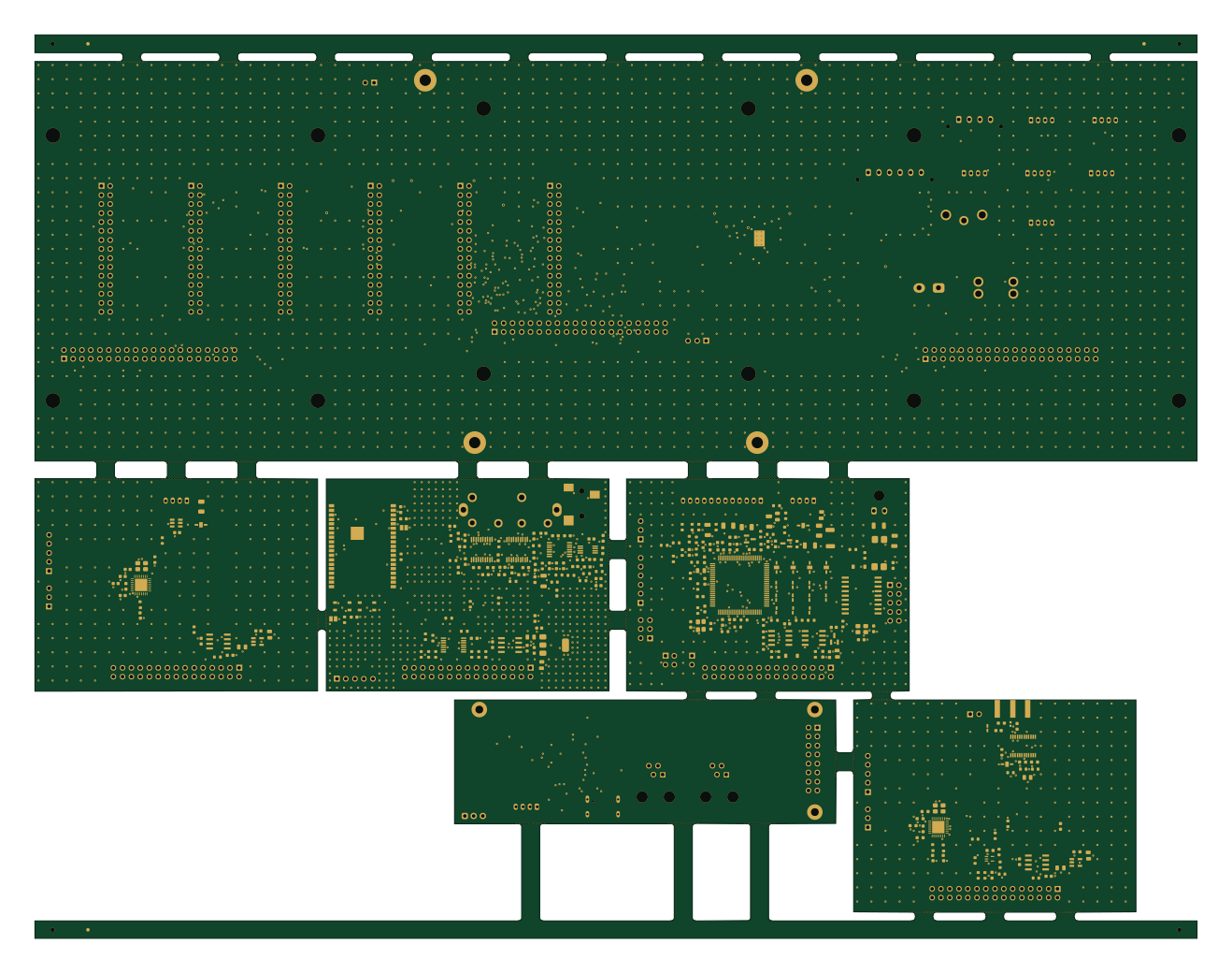
329 × 255.5 mm483 parts4LMIT6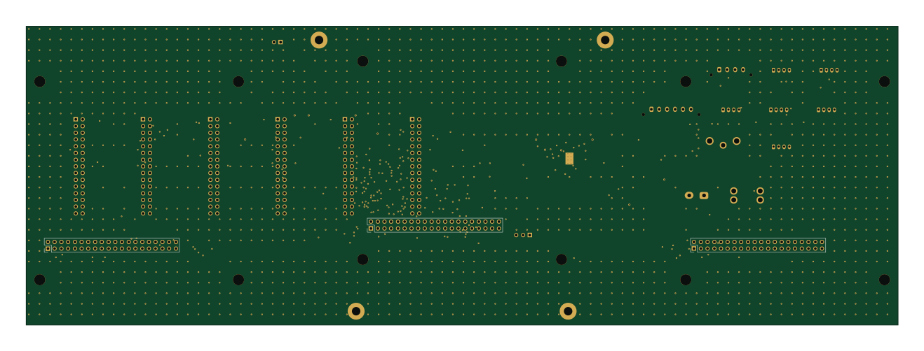
DigiDash2
329 × 113 mm179 parts4LMIT6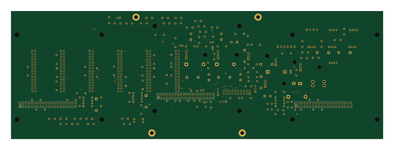
DigiDash3
329 × 113 mm150 parts2LMIT6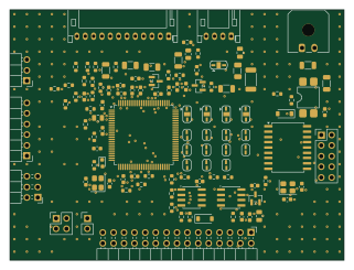 AVR/Arduino
SensorCard
80 × 60 mm114 parts4LMIT6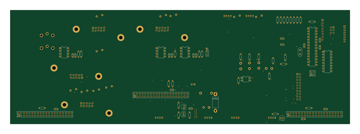 AVR/Arduino
DigiDash
309 × 103.5 mm97 parts2LMIT6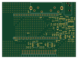 ESP32
AudioCarrier
80 × 60 mm77 parts2LMIT6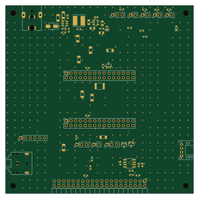
BenchBoard
100 × 100 mm67 parts2LMIT6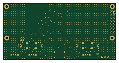 ESP32
ConsoleBoard
100 × 50 mm60 parts4LMIT6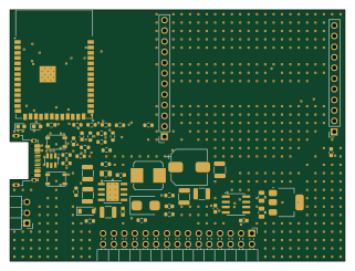 ESP32
LTECard
80 × 60 mm58 parts4LMIT6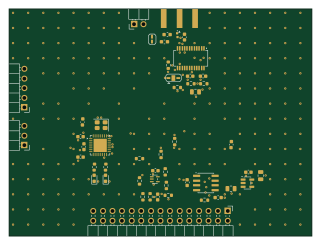 STM32
RadioCard
80 × 60 mm50 parts2LMIT6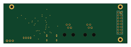 ESP32
ConsoleBoardRS
108 × 35 mm42 parts2LMIT6
Similar boards
 STM32
LumenPnP Motherboard
opulo-inc
149 × 95 mm296 parts4LCC-BY-SA-4.03.7k STM32
Type g
google
169 × 30 mm24 parts2LApache-2.02.9k STM32
Base
52.3 × 52.3 mm36 parts2LApache-2.02.9k STM32
Type a
150 × 30 mm14 parts2LApache-2.02.9k STM32
Main panel
234 × 84 mm26 parts4LApache-2.02.9k STM32
Type c
188 × 30 mm17 parts2LApache-2.02.9k