
Minimal-UART-Computer-3

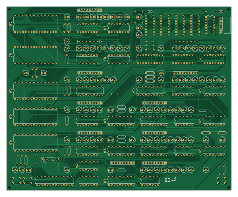
About the Minimal-UART-Computer-3 PCB
Minimal-UART-Computer-3 is an open source AVR/Arduino PCB design by slu4coder, published on GitHub. It is a 2-layer board measuring 208.9 × 170.8 mm, with 202 components from 58 distinct parts.
Its main chip is the ATmega328P, from the AVR/Arduino family. Other key parts include the 74HC00, 74HC193, 74HC161, 74HC595 and 74HC165. By type, the board carries 98 diodes, 43 resistors, 36 ICs, 20 capacitors, 3 switches and 1 crystal.
It belongs with the retro computing designs in this gallery.
From the project
Version 3 of my educational DIY TTL computer built around a UART serial interface - now with blinkenlights!
Here comes a big update of my DIY 'Minimal UART Computer', a machine built around a serial interface just from a handful of logic ICs, RAM and FLASH memory. For it's size, simplicity and self-imposed limitations, it's got double the processing power of a Commodore C64 or Apple II. It's mission is to be a fun learning platform for understanding computers on a fundamental level.
Main components on the Minimal-UART-Computer-3
Minimal-UART-Computer-3 bill of materials (BOM)
202 components, 58 distinct parts.
| Qty | Part | Footprint | Refs |
|---|---|---|---|
| 2 | 74HC00 | DIP-14_W7.62mm | U1, U35 |
| 1 | 74HC193 | DIP-16_W7.62mm | U2 |
| 11 | 74HC161 | DIP-16_W7.62mm | U3, U6, U10, U14, U16, U18, U19, U25 +3 |
| 1 | 74HC595 | DIP-16_W7.62mm | U4 |
| 1 | 74HC165 | DIP-16_W7.62mm | U5 |
| 1 | SST39SF010 HSB | DIP-32_W15.24mm | U7 |
| 3 | 74HC377 | DIP-20_W7.62mm | U8, U21, U23 |
| 1 | SST39SF010 MSB | DIP-32_W15.24mm | U9 |
| 1 | SST39SF010 LSB | DIP-32_W15.24mm | U11 |
| 1 | 74HC32 | DIP-14_W7.62mm | U12 |
| 2 | 74HC283 | DIP-16_W7.62mm | U13, U33 |
| 1 | SST39SF010 SSD | DIP-32_W15.24mm | U15 |
| 1 | AS6C1008 RAM | DIP-32_W15.24mm | U17 |
| 5 | 74HC245 | DIP-20_W7.62mm | U20, U22, U24, U27, U34 |
| 2 | 74HC86 | DIP-14_W7.62mm | U30, U31 |
| 1 | 74HC4002 | DIP-14_W7.62mm | U32 |
| 1 | ATmega328P | DIP-28_W7.62mm | U36 |
| 1 | 16MHz | Crystal_HC18-U_Vertical | Y1 |
| 1 | UART | PinSocket_1x06_P2.54mm_Vertical | J1 |
| 1 | RESET | SW_PUSH_6mm | SW1 |
Show 38 more
| Qty | Part | Footprint | Refs |
|---|---|---|---|
| 1 | SINGLE | SW_PUSH_6mm | SW2 |
| 1 | SELECT | SW_PUSH_6mm | SW3 |
| 72 | LED_Small | LED_D5.0mm | D1, D2, D3, D4, D5, D6, D7, D8 +64 |
| 1 | N | LED_D5.0mm | D59 |
| 1 | AI | LED_D5.0mm | D65 |
| 1 | AO | LED_D5.0mm | D66 |
| 1 | BI | LED_D5.0mm | D76 |
| 1 | BO | LED_D5.0mm | D77 |
| 1 | EO | LED_D5.0mm | D78 |
| 1 | CIH | LED_D5.0mm | D79 |
| 1 | TO | LED_D5.0mm | D80 |
| 1 | COH | LED_D5.0mm | D81 |
| 1 | RI | LED_D5.0mm | D82 |
| 1 | COL | LED_D5.0mm | D83 |
| 1 | CIL | LED_D5.0mm | D84 |
| 1 | MIL | LED_D5.0mm | D85 |
| 1 | MIH | LED_D5.0mm | D86 |
| 1 | TI | LED_D5.0mm | D87 |
| 1 | ME | LED_D5.0mm | D88 |
| 1 | FI | LED_D5.0mm | D89 |
| 1 | II | LED_D5.0mm | D90 |
| 1 | IC | LED_D5.0mm | D91 |
| 1 | CE | LED_D5.0mm | D92 |
| 1 | EC | LED_D5.0mm | D93 |
| 1 | ES | LED_D5.0mm | D94 |
| 1 | C | LED_D5.0mm | D95 |
| 1 | R | LED_D5.0mm | D97 |
| 1 | RO | LED_D5.0mm | D99 |
| 1 | CLK | LED_D5.0mm | D100 |
| 2 | 22p | C_Disc_D5.0mm_W2.5mm_P2.50mm | C1, C2 |
| 18 | 100n | C_Disc_D3.0mm_W2.0mm_P2.50mm | C3, C4, C5, C6, C7, C8, C9, C10 +10 |
| 14 | 470 | R_Axial_DIN0207_L6.3mm_D2.5mm_P7.62mm_Horizontal | R1, R2, R7, R9, R12, R15, R17, R18 +6 |
| 1 | 10k | R_Axial_DIN0207_L6.3mm_D2.5mm_P7.62mm_Horizontal | R3 |
| 5 | 3.3k | R_Axial_DIN0207_L6.3mm_D2.5mm_P7.62mm_Horizontal | R4, R5, R6, R28, R33 |
| 11 | 2k | R_Axial_DIN0207_L6.3mm_D2.5mm_P7.62mm_Horizontal | R8, R10, R11, R13, R14, R16, R21, R25 +3 |
| 1 | 1k | R_Axial_DIN0207_L6.3mm_D2.5mm_P7.62mm_Horizontal | R30 |
| 1 | 470 | R_Array_SIP9 | RN1 |
| 10 | 3.3k | R_Array_SIP9 | RN2, RN3, RN4, RN5, RN6, RN7, RN8, RN9 +2 |
Minimal-UART-Computer-3 design files
The KiCad project lives in the slu4coder/Minimal-UART-Computer-3 repository on GitHub; these links point at the commit this page was built from.
- LayoutKiCAD9/8-Bit CPU 32k.kicad_pcb
- SchematicKiCAD9/8-Bit CPU 32k.kicad_sch
Minimal-UART-Computer-3: common questions
What microcontroller does the Minimal-UART-Computer-3 use?
The Minimal-UART-Computer-3 is built around the ATmega328P, from the AVR/Arduino family.
How big is the Minimal-UART-Computer-3 PCB?
The Minimal-UART-Computer-3 measures 208.9 × 170.8 mm, has 2 copper layers and is 1.6 mm thick.
How many components are on the Minimal-UART-Computer-3?
202 components, from 58 distinct parts. The full bill of materials is listed on this page.
Where can I download the Minimal-UART-Computer-3 design files?
From the slu4coder/Minimal-UART-Computer-3 repository on GitHub, which has the KiCad layout and the schematic; the links under Design files point to each one.
Can I use the Minimal-UART-Computer-3 design in my own project?
The repository has no license, so all rights stay with slu4coder. Use it as a reference, and ask the author before reusing the design.
Can I test firmware for the Minimal-UART-Computer-3 without the hardware?
Yes. HardLabs builds a simulation of the board from its netlist and BOM, so you can run and debug AVR/Arduino firmware against it before you order a PCB.
Similar boards
 AVR/Arduino
Redox keyboard
mattdibi
162.2 × 126.5 mm77 parts2LMIT2.0k AVR/Arduino
ModuleV450
stuartpittaway
30 × 61.4 mm39 parts2LCC-BY-NC-4.01.1k AVR/Arduino
V4
30 × 50 mm38 parts2LCC-BY-NC-4.01.1k AVR/Arduino
Discipline
coseyfannitutti
304.9 × 122.8 mm170 parts2LCC-BY-NC-4.01.0k AVR/Arduino
Megadesk
gcormier
41.7 × 32.2 mm23 parts2LGPL-3.0818 AVR/Arduino
Easyduino Atmega Nano
Hanqaqa
43.4 × 18 mm30 parts4LCERN-OHL-P-2.0746