
PowerControlModule

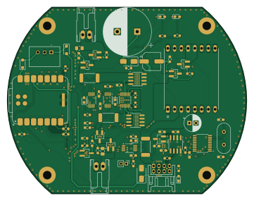
About the PowerControlModule PCB
PowerControlModule is an open source RP2040/RP2350 PCB design by tokai-student-rocket-project, published on GitHub. It is a 2-layer board measuring 90 × 70 mm, with 80 components from 40 distinct parts.
Its main chip is the XIAO-RP2040-DIP, from the RP2040/RP2350 family. Other key parts include the MCP2515-XST, INA228, LTC4353, MCP2562-E-SN and MCP1792X-5002XCB. By type, the board carries 27 resistors, 18 capacitors, 11 diodes, 9 ICs, 9 transistors and 3 connectors.
From the project
H-62搭載計器 すばる1.3 | 2025年度 夏季 能代 NOGO
- 水密機能の搭載 - 基板径をΦ90に変更 - LYLYGO開発ボードを活用した地上局
Flight : 搭載計器のソースコード - Flight Module - Power Module - Sensing Module - Valve Control Module
Ground : 地上局のソースコード - Ground Flight Module - Ground Sensing Module - Sea Flight Module - Teleplot Ground Flight Module - Teleplot Layout
LogDumper : ログ読み出しのソースコード - Flight Module - Sensing Module
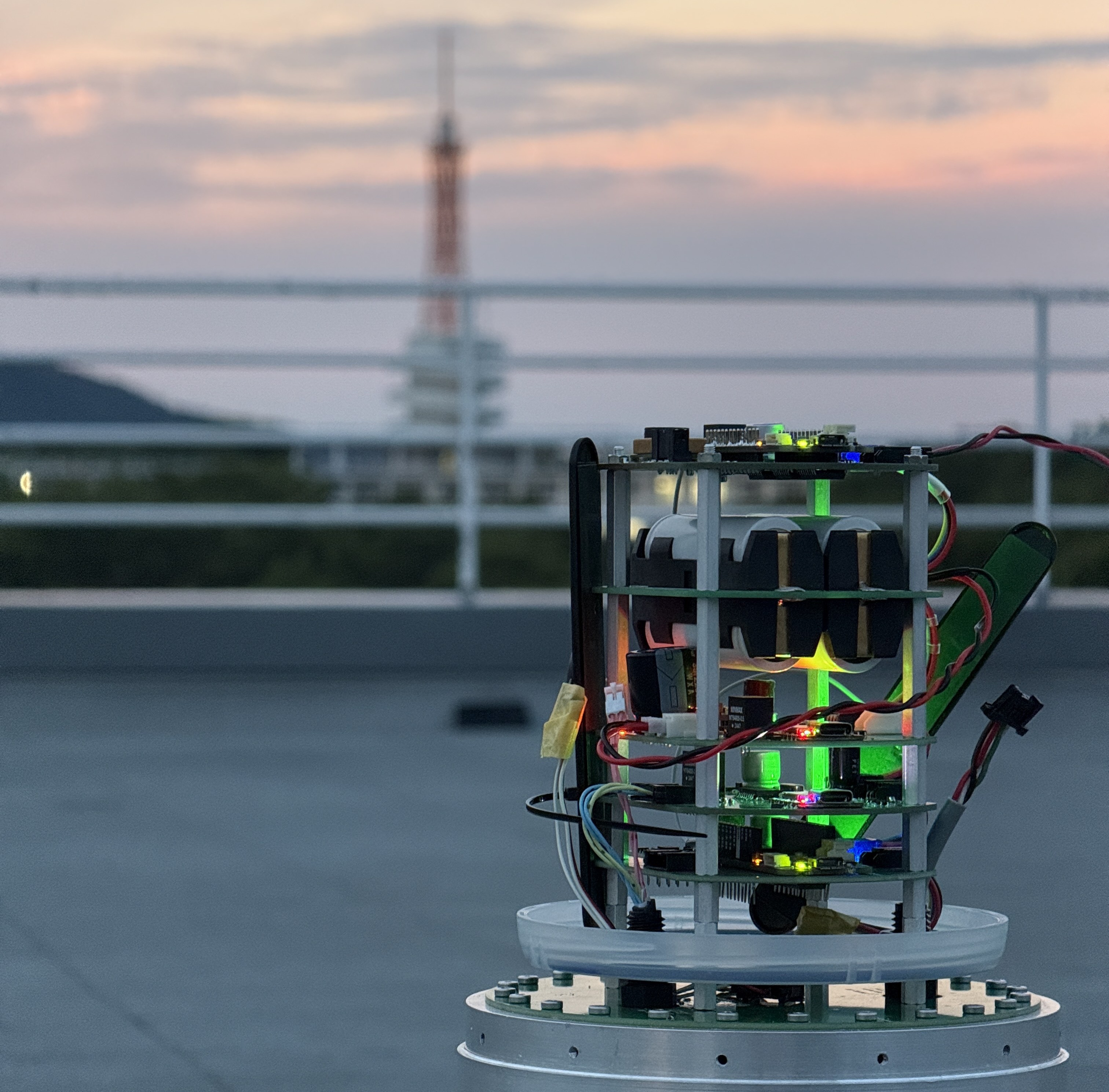
Main components on the PowerControlModule
PowerControlModule bill of materials (BOM)
80 components, 40 distinct parts — part numbers from the project's BOM.
| Qty | Part | Footprint | Refs |
|---|---|---|---|
| 1 | XIAO-RP2040-DIP | XIAO-RP2040-SMD | U1 |
| 1 | MCP2515-XST MCP2515-xST | TSSOP-20_4.4x6.5mm_P0.65mm | U2 |
| 3 | INA228 | VSSOP-10_3x3mm_P0.5mm | U3, U4, U6 |
| 1 | LTC4353 | MSOP-16_3x4.039mm_P0.5mm | U5 |
| 1 | MCP2562-E-SN | SOIC-8_3.9x4.9mm_P1.27mm | U8 |
| 1 | MCP1792X-5002XCB MCP1792x-5002xCB | SOT-23_Handsoldering | U9 |
| 1 | LTC3119 | StrawberryLinux_LTC3119 | U11 |
| 6 | AO3401A | SOT-23_Handsoldering | Q1, Q2, Q4, Q5, Q7, Q9 |
| 1 | AO3400A | TSOT-23_HandSoldering | Q3 |
| 2 | SI4162DY Si4162DY | SOIC-8_3.9x4.9mm_P1.27mm | Q11, Q12 |
| 1 | 8MHZ 8MHz | Crystal_HC49-4H_Vertical | Y1 |
| 2 | DF1B-2S-2.5R | DF1B-2S-2.5R | J1, J2 |
| 1 | DF11-8DP-2DS | DF11-8DP-2DS | J3 |
| 1 | M78AR05-0.5 | M78AR03305 | PS1 |
| 1 | Thermistor_NTC | PinHeader_1x02_P2.00mm_Vertical | TH1 |
| 2 | Orange | LED_0603_1608Metric_Pad1.05x0.95mm_HandSolder | D1, D2 |
| 1 | Green | LED_0603_1608Metric_Pad1.05x0.95mm_HandSolder | D3 |
| 2 | SMAJ45A | D_SMA | D4, D5 |
| 3 | SS2040FL | D_SOD-123F | D6, D10, D11 |
| 3 | Red | LED_0603_1608Metric_Pad1.05x0.95mm_HandSolder | D7, D8, D9 |
Show 20 more
| Qty | Part | Footprint | Refs |
|---|---|---|---|
| 1 | 220UF 220uF | CP_Radial_D6.3mm_P2.50mm | C1 |
| 2 | 22UF 22uF | C_0805_2012Metric_Pad1.18x1.45mm_HandSolder | C2, C4 |
| 6 | 0.1UF 0.1uF | C_0603_1608Metric_Pad1.08x0.95mm_HandSolder | C3, C5, C13, C16, C17, C22 |
| 1 | 2200UF 2200uF | CP_Radial_D18.0mm_P7.50mm | C9 |
| 1 | 0.1UF 0.1uF | C_0603_1608Metric | C10 |
| 1 | 33UF 33uF | CP_Elec_6.3x5.9 | C11 |
| 2 | 15PF 15pF | C_0603_1608Metric_Pad1.08x0.95mm_HandSolder | C14, C15 |
| 2 | 0.056UF 0.056uF | L_0603_1608Metric | C18, C21 |
| 2 | 2.2UF 2.2uF | C_0603_1608Metric_Pad1.08x0.95mm_HandSolder | C19, C20 |
| 4 | 4.7KR 4.7kR | R_0603_1608Metric_Pad0.98x0.95mm_HandSolder | R1, R2, R8, R23 |
| 6 | 10KR 10kR | R_0603_1608Metric_Pad0.98x0.95mm_HandSolder | R3, R6, R7, R22, R24, R26 |
| 3 | 5.6KR 5.6kR | R_0603_1608Metric_Pad0.98x0.95mm_HandSolder | R4, R18, R19 |
| 2 | 3.3KR 3.3kR | R_0603_1608Metric_Pad0.98x0.95mm_HandSolder | R5, R20 |
| 3 | 680R | R_0603_1608Metric_Pad0.98x0.95mm_HandSolder | R9, R13, R14 |
| 3 | 15MR 15mR | R_2512_6332Metric_Pad1.40x3.35mm_HandSolder | R10, R11, R12 |
| 2 | 2.7KR 2.7kR | R_0603_1608Metric_Pad0.98x0.95mm_HandSolder | R15, R16 |
| 1 | 820 | R_0603_1608Metric_Pad0.98x0.95mm_HandSolder | R17 |
| 1 | 3.6KR 3.6kR | R_0603_1608Metric_Pad0.98x0.95mm_HandSolder | R21 |
| 1 | 120R | R_0603_1608Metric_Pad0.98x0.95mm_HandSolder | R25 |
| 1 | 10K 10k | R_0603_1608Metric | R27 |
PowerControlModule design files
The KiCad project lives in the tokai-student-rocket-project/H-62-Avionics repository on GitHub; these links point at the commit this page was built from.
PowerControlModule: common questions
What microcontroller does the PowerControlModule use?
The PowerControlModule is built around the XIAO-RP2040-DIP, from the RP2040/RP2350 family.
How big is the PowerControlModule PCB?
The PowerControlModule measures 90 × 70 mm, has 2 copper layers and is 1.6 mm thick.
How many components are on the PowerControlModule?
80 components, from 40 distinct parts, with part numbers taken from the project's own BOM. The full bill of materials is listed on this page.
Where can I download the PowerControlModule design files?
From the tokai-student-rocket-project/H-62-Avionics repository on GitHub, which has the KiCad layout, the schematic and the BOM; the links under Design files point to each one.
Can I use the PowerControlModule design in my own project?
The repository has no license, so all rights stay with tokai-student-rocket-project. Use it as a reference, and ask the author before reusing the design.
Can I test firmware for the PowerControlModule without the hardware?
Yes. HardLabs builds a simulation of the board from its netlist and BOM, so you can run and debug RP2040/RP2350 firmware against it before you order a PCB.
More boards in H-62-Avionics
 AVR/Arduino
FlightModule
90 × 70 mm70 parts2LNo license0 RP2040/RP2350
ValveControlModule
90 × 70 mm48 parts2LNo license0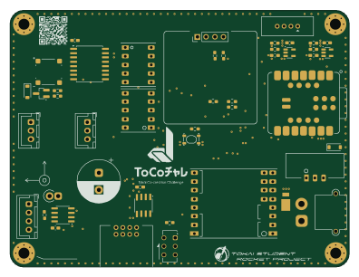 Renesas
THRValveControlModule
99 × 75 mm46 parts2LNo license0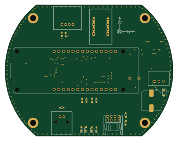 AVR/Arduino
SensingModule
90 × 70 mm44 parts2LNo license0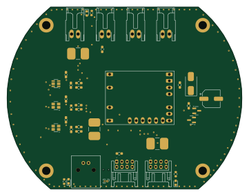
PowerModule
90 × 70 mm41 parts2LNo license0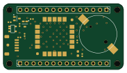 AVR/Arduino
MKRGPSShield V4.0
45.7 × 25 mm34 parts2LNo license0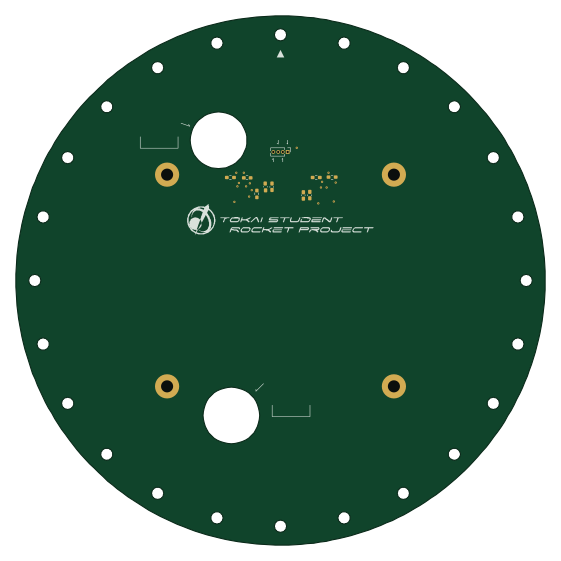
SubaruPlate
140 × 140 mm12 parts2LNo license0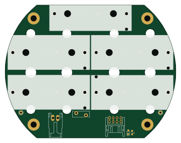
BatteryModule
90 × 70 mm12 parts2LNo license0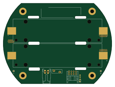
18650BatteryModule
93.9 × 70 mm11 parts2LNo license0
FeRAMTestBoard
21.3 × 21.3 mm5 parts2LNo license0
Similar boards
 RP2040/RP2350
OSO-BOOK-C1
joeycastillo
85 × 115 mm29 parts2LCC-BY-SA-4.08.1k RP2040/RP2350
Corne cherry
foostan
277.2 × 107.5 mm164 parts2LCC-BY-4.07.7k RP2040/RP2350
Corne chocolate
277.2 × 107.5 mm164 parts2LCC-BY-4.07.7k RP2040/RP2350
Jitx design
gusmanb
55.5 × 65 mm26 parts4LGPL-3.05.0k RP2040/RP2350
LogicAnalyzer
57 × 55.2 mm6 parts2LGPL-3.05.0k RP2040/RP2350
Main
google
98 × 71 mm102 parts2LApache-2.02.9k