
0xCB 1337

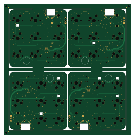
About the 0xCB 1337 PCB
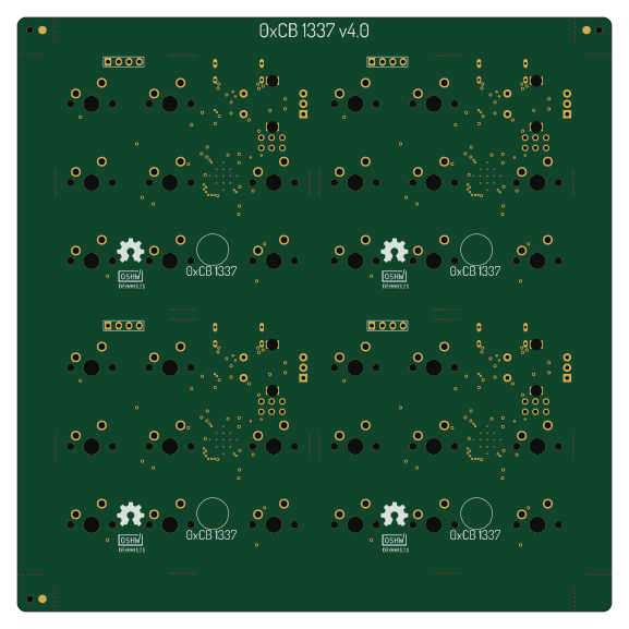
0xCB 1337 is an open source RP2040/RP2350 PCB design by 0xCB-dev, published on GitHub under the Custom license license. It is a 4-layer board measuring 137 × 141 mm, with 114 components from 25 distinct parts.
Its main chip is the RP2040, from the RP2040/RP2350 family. Other key parts include the USBLC6-2P6, XC6210B332MR-G, TPS2553DBVR, SN74LVC1T45DRLR and W25Q32JVUUIQ. By type, the board carries 51 capacitors, 31 diodes, 11 resistors, 6 ICs, 2 connectors and 2 inductors.
It belongs with the keyboards and displays & leds designs in this gallery.
From the project
Mechanical macropad with OLED running QMK
Licence | OSHWA :-------------------------:|:-------------------------: | [](https://certification.oshwa.org/de000121.html)
qmk clone cd qmkfirmware export LTO=Y Press switch 1 while plugging in to go into dfu mode (or the reset button) make 0xcb/1337:via:flash
You can use the humanpnp to easily place components.
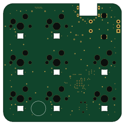
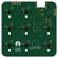
Top | Bottom :-------------------------:|:-------------------------: |
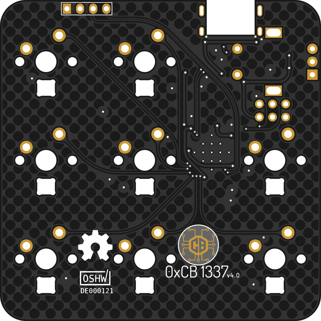
Main components on the 0xCB 1337
0xCB 1337 bill of materials (BOM)
114 components, 25 distinct parts — part numbers from the project's BOM.
| Qty | Part | Footprint | Refs |
|---|---|---|---|
| 1 | USBLC6-2P6 TECH PUBLIC | SOT-666 | U1 |
| 1 | XC6210B332MR-G Torex Semiconductor | SOT-23-5 | U2 |
| 1 | TPS2553DBVR | SOT95P280X145-6N | U3 |
| 1 | SN74LVC1T45DRLR 74LVC1T45 Texas Instruments | SOT-563 | U4 |
| 1 | W25Q32JVUUIQ Winbond | W25Q32JVUUIQ | U5 |
| 1 | RP2040 Raspberry Pi | RP2040-QFN-56 | U6 |
| 1 | 2TJ412000HYGBC 12MHz JYJE | Crystal_SMD_2520-4Pin_2.5x2.0mm | Y1 |
| 1 | GT-USB-7014C USB_C_Receptacle_USB2.0 G-Switch | GT-USB-7014C | J1 |
| 1 | C388698 FPC | FFC-SMD_12P-P0.50_X05B20U12T | J2 |
| 1 | MF-FSMF050X-2 1A BOURNS | Fuse_0603_1608Metric | F1 |
| 8 | C5156480 MX | SW_Hotswap_Kailh_1.00u | MX1, MX2, MX4, MX5, MX6, MX7, MX8, MX9 |
| 1 | EC11 | EC11 | MX3 |
| 8 | SK6812MINI-E | MX_SK6812MINI-E | D1, D2, D3, D4, D5, D6, D7, D8 |
| 23 | WS2812B-2020 WS2812B Worldsemi | LED_WS2812B-2020_PLCC4_2.0x2.0mm | D9, D10, D11, D12, D13, D14, D15, D16 +15 |
| 2 | BLM15PX601SN1D 600R Murata Electronics | R_0402_1005Metric | FB1, FB2 |
| 44 | CL05B104KO5NNNC 100n Samsung Electro-Mechanics | C_0201_0603Metric | C1, C2, C3, C4, C5, C6, C7, C8 +36 |
| 3 | CL05A106MQ5NUNC 10u Samsung Electro-Mechanics | C_0402_1005Metric | C10, C11, C17 |
| 2 | CL05A105KA5NQNC 1u Samsung Electro-Mechanics | C_0201_0603Metric | C22, C26 |
| 2 | 0402CG150J500NT 15p FH(Guangdong Fenghua Advanced Tech) | C_0201_0603Metric | C37, C40 |
| 2 | 0402WGF5101TCE 5k1 UNI-ROYAL(Uniroyal Elec) | R_0201_0603Metric | R1, R2 |
Show 5 more
| Qty | Part | Footprint | Refs |
|---|---|---|---|
| 3 | 0402WGF270JTCE 27R UNI-ROYAL(Uniroyal Elec) | R_0201_0603Metric | R3, R8, R9 |
| 2 | 0402WGF1002TCE 10k UNI-ROYAL(Uniroyal Elec) | R_0201_0603Metric | R4, R7 |
| 1 | 0402WGF1002TCE 75k UNI-ROYAL(Uniroyal Elec) | R_0201_0603Metric | R5 |
| 2 | 0402WGF1001TCE 1k UNI-ROYAL(Uniroyal Elec) | R_0201_0603Metric | R6, R10 |
| 1 | 10K 10k | R_Array_Convex_4x0603 | RN1 |
0xCB 1337 design files
The KiCad project lives in the 0xCB-dev/0xCB-1337 repository on GitHub; these links point at the commit this page was built from.
0xCB 1337: common questions
What microcontroller does the 0xCB 1337 use?
The 0xCB 1337 is built around the RP2040, from the RP2040/RP2350 family.
How big is the 0xCB 1337 PCB?
The 0xCB 1337 measures 137 × 141 mm, has 4 copper layers and is 1.6062 mm thick.
How many components are on the 0xCB 1337?
114 components, from 25 distinct parts, with part numbers taken from the project's own BOM. The full bill of materials is listed on this page.
Where can I download the 0xCB 1337 design files?
From the 0xCB-dev/0xCB-1337 repository on GitHub, which has the KiCad layout and the BOM; the links under Design files point to each one.
Can I use the 0xCB 1337 design in my own project?
It is published under Custom license, which limits how it may be reused; read the license before building on it.
Can I test firmware for the 0xCB 1337 without the hardware?
Yes. HardLabs builds a simulation of the board from its netlist and BOM, so you can run and debug RP2040/RP2350 firmware against it before you order a PCB.
More boards in 0xCB-1337
Similar boards
 RP2040/RP2350
Open Book Abridged Edition
joeycastillo
85 × 115 mm29 parts2LCC-BY-SA-4.08.1k RP2040/RP2350
Corne
foostan
277.2 × 107.5 mm164 parts2LCC-BY-4.07.7k RP2040/RP2350
Corne
277.2 × 107.5 mm164 parts2LCC-BY-4.07.7k RP2040/RP2350
Open Source Smart Glasses
Mentra-Community
93 × 10.5 mm80 parts4LMIT1.2k RP2040/RP2350
MSA
30.5 × 138 mm61 parts2LMIT1.2k RP2040/RP2350
Msa
47.8 × 9.4 mm53 parts2LMIT1.2k