
Hermod right


About the Hermod right PCB
Hermod right is an open source STM32 PCB design by modern-hobbyist, published on GitHub under the MIT license. It is a 2-layer board measuring 3.6 × 3.3 mm, with 212 components from 29 distinct parts.
Its main chip is the STM32G474CETx, from the STM32 family. Other key parts include the SRV05-4, XC6206PXXXMR-REGULATOR_LINEAR, CR2013-MI2120 and SN74AHCT1G125DBVR. By type, the board carries 57 capacitors, 46 diodes, 44 LEDs, 8 ICs, 6 resistors and 3 connectors.
It belongs with the keyboards and displays & leds designs in this gallery.
From the project
Collection of KiCad PCB designs for custom keyboards, including full-sized and split ergonomic layouts with STM32F072CBT6 microcontrollers.
Hermod Mk. III is a redesign of my original Hermod split keyboard. Some issues that were resolved in this version include: - Updated from the PRTR5V0U2X,215 to the SRV05-4 since the former is out of stock everywhere.
Furthermore, this is the NORTH FACING MX Spacing variant. While it is functionally identically to the Hermod Mk. II, this layout is spaced in a 19.05x19.05 grid, which makes it compatible with the Tai-Hao keycaps highlighted in the ZSA Voyager. Also, the switches are rotated 180• from the previous versions so that the LED's are better aligned with shine-through keycaps.
Main components on the Hermod right
Hermod right bill of materials (BOM)
212 components, 29 distinct parts — part numbers from the project's BOM.
| Qty | Part | Footprint | Refs |
|---|---|---|---|
| 1 | STM32G474CETx | LQFP-48_7x7mm_P0.5mm | U1 |
| 2 | SRV05-4 | SOT-23-6-routable | U2, U9 |
| 1 | XC6206PXXXMR-REGULATOR_LINEAR XC6206PxxxMR-Regulator_Linear | SOT-23 | U3 |
| 1 | CR2013-MI2120 | CR2013-MI2120 | U4 |
| 1 | SN74AHCT1G125DBVR ~ | Pogo_2.54mm_5p | U6 |
| 1 | ~ | Pogo_2.54mm_5p | U7 |
| 1 | SN74AHCT1G125DBVR | SOT95P280X145-5N | U8 |
| 1 | MMUN2133LT1G | SOT-23-3 | Q3 |
| 1 | 78171-0004 USB_C_Receptacle_USB2.0 | USB_C_Receptacle_HRO_TYPE-C-31-M-14 | J1 |
| 1 | CONN_01X05 Conn_01x05 | PinHeader_1x05_P2.54mm_Vertical | J2 |
| 1 | USB_C_Receptacle_USB2.0 | USB_C_Receptacle_HRO_TYPE-C-31-M-14 | J3 |
| 36 | KS33_SW_HS KS33_SW_solder | KS33_Choc-v2_HS_1U | CH1, CH2, CH3, CH4, CH5, CH6, CH8, CH9 +28 |
| 8 | KS33_SW_HS KS33_SW_solder | KS33_Choc-v2_HS_1.5U | CH7, CH14, CH21, CH28, CH35, CH38, CH39, CH40 |
| 2 | 500mA | Fuse_1206_3216Metric | F1, F2 |
| 1 | DFU | SW_SPST_TL3342 | RESET1 |
| 44 | CHOC_SK6812MINI-E choc_SK6812MINI-E | LED_choc_6028R | LED1, LED2, LED3, LED4, LED5, LED6, LED7, LED8 +36 |
| 42 | D | D_SOD-123 | D1, D2, D3, D4, D5, D6, D7, D8 +34 |
| 2 | 1N4148 D | D_SOD-123 | D40, D41 |
| 2 | 1N4148 | D_SOD-123 | D45, D46 |
| 45 | 0.1UF 0.1uF | C_0402_1005Metric | C1, C2, C3, C4, C5, C6, C7, C8 +37 |
Show 9 more
| Qty | Part | Footprint | Refs |
|---|---|---|---|
| 1 | 0.1UF 10uF | C_0603_1608Metric | C45 |
| 5 | 0.1UF 100nF | C_0402_1005Metric | C46, C47, C48, C49, C100 |
| 3 | 0.1UF 100n | C_0805_2012Metric | C50, C51, C52 |
| 2 | 100NF 1uF | C_0402_1005Metric | C108, C109 |
| 1 | 100NF 100nF | C_0402_1005Metric | C110 |
| 3 | 5.1k | R_0402_1005Metric | R1, R2, R5 |
| 1 | 120 | R_0805_2012Metric | R6 |
| 1 | 120 68k | R_0805_2012Metric | R7 |
| 1 | 68K 68k | R_0805_2012Metric | R9 |
Hermod right design files
The KiCad project lives in the modern-hobbyist/aesir repository on GitHub; these links point at the commit this page was built from.
Hermod right: common questions
What microcontroller does the Hermod right use?
The Hermod right is built around the STM32G474CETx, from the STM32 family.
How big is the Hermod right PCB?
The Hermod right measures 3.6 × 3.3 mm, has 2 copper layers and is 1.6 mm thick.
How many components are on the Hermod right?
212 components, from 29 distinct parts, with part numbers taken from the project's own BOM. The full bill of materials is listed on this page.
Where can I download the Hermod right design files?
From the modern-hobbyist/aesir repository on GitHub, which has the KiCad layout, the schematic and the BOM; the links under Design files point to each one.
Can I use the Hermod right design in my own project?
Yes, under the terms of its MIT license, which modern-hobbyist chose for the repository.
Can I test firmware for the Hermod right without the hardware?
Yes. HardLabs builds a simulation of the board from its netlist and BOM, so you can run and debug STM32 firmware against it before you order a PCB.
More boards in aesir
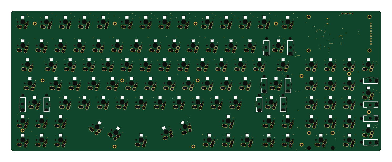 STM32
Mist
372.1 × 141.2 mm445 parts2LMIT27 STM32
Heimdall
405.4 × 159 mm316 parts4LMIT27 STM32
Hermod left
3.6 × 3.3 mm196 parts2LMIT27 STM32
Modern lcd keyboard
72 × 44.5 mm184 parts2LMIT27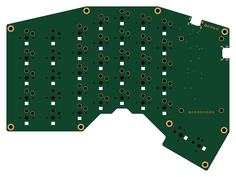 STM32
Hermod
189.2 × 139.5 mm177 parts2LMIT27 STM32
Paste
3.6 × 3.3 mm72 parts2LMIT27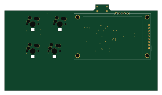 STM32
Stm32G474RETx template
134.5 × 76 mm46 parts2LMIT27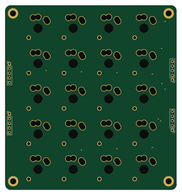
Numpad
92.1 × 99.3 mm44 parts2LMIT27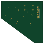 STM32
Modern keyboard template
44 × 44.1 mm25 parts2LMIT27
Similar boards
 STM32
LumenPnP Motherboard
opulo-inc
149 × 95 mm296 parts4LCC-BY-SA-4.03.7k STM32
Type g
google
169 × 30 mm24 parts2LApache-2.02.9k STM32
Type a
150 × 30 mm14 parts2LApache-2.02.9k STM32
Base
52.3 × 52.3 mm36 parts2LApache-2.02.9k STM32
Main panel
234 × 84 mm26 parts4LApache-2.02.9k STM32
Type c
188 × 30 mm17 parts2LApache-2.02.9k