
AS3397-Conductor

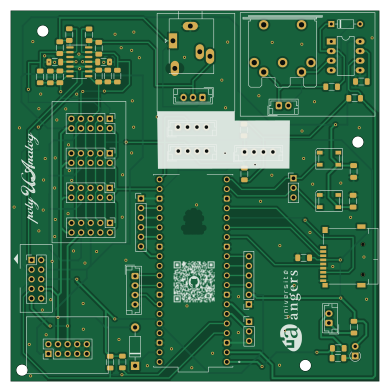
About the AS3397-Conductor PCB
AS3397-Conductor is an open source Raspberry Pi PCB design by PhysicsDptAngers, published on GitHub under the MIT license. It is a 2-layer board measuring 97.3 × 97.8 mm, with 53 components from 32 distinct parts.
Its main chip is the SC0918, from the Raspberry Pi family. Other key parts include the 6N138 and OPA1679. By type, the board carries 20 connectors, 16 resistors, 9 capacitors, 5 diodes, 2 ICs and 1 module.
It belongs with the audio and iot & wireless designs in this gallery.
From the project
Open source, analog and polyphonic synthesizer
The Conductor Card serves as the central hub for the synthesizer, managing communication, power distribution, and analog signal summing. Its architecture is designed to interface external controls with internal voice modules.
The card manages multiple communication protocols to interface with the outside world:
MIDI: Standard MIDI IN port and an optional MIDI OUT header. I2C: Dedicated header for optional "Controllers" (e.g., a front panel equipped with knobs and sliders for real-time parameter control). Dedicated header for optional "FX card" Wireless (UDP): Support for UDP over Wi-Fi when…
Main components on the AS3397-Conductor
AS3397-Conductor bill of materials (BOM)
53 components, 32 distinct parts.
| Qty | Part | Footprint | Refs |
|---|---|---|---|
| 1 | 6N138 | DIP-8_W7.62mm_LongPads | U2 |
| 1 | OPA1679 | SOIC-14_3.9x8.7mm_P1.27mm | U3 |
| 1 | SC0918 | MODULE_SC0918 | A1 |
| 1 | Micro_SD_Card | J_SD_Card-micro_socket_A | J1 |
| 1 | ADC_connector | JST_EH_B4B-EH-A_1x04_P2.50mm_Vertical | J2 |
| 1 | Conn_01x06_Socket | PinHeader_1x06_P2.54mm_Vertical | J3 |
| 3 | I2C controller | JST_EH_B4B-EH-A_1x04_P2.50mm_Vertical | J4, J11, J15 |
| 2 | Conn_01x02_Socket | JST_EH_B2B-EH-A_1x02_P2.50mm_Vertical | J5, J14 |
| 1 | AudioJack3 | Jack_3.5mm_Ledino_KB3SPRS_Horizontal | J6 |
| 1 | Conn_POWER | PinHeader_2x05_P2.54mm_Vertical | J7 |
| 1 | MIDI IN | MIDI_DIN5 | J8 |
| 1 | Conn_FX_1 | PinHeader_2x05_P2.54mm_Vertical | J9 |
| 1 | Conn_FX_2 | PinHeader_2x05_P2.54mm_Vertical | J10 |
| 1 | Conn_01x03_Socket_AudioOUT | JST_EH_B3B-EH-A_1x03_P2.50mm_Vertical | J12 |
| 1 | Conn_FX_3 | PinHeader_2x05_P2.54mm_Vertical | J13 |
| 1 | Conn_01x06_Socket_SPI | PinSocket_1x06_P2.54mm_Vertical | J16 |
| 2 | Conn_01x03_Socket | PinHeader_1x03_P2.54mm_Vertical | J17, J18 |
| 1 | Conn_Voice | PinHeader_2x05_P2.54mm_Vertical | J19 |
| 1 | Conn_FX_4 | PinHeader_2x05_P2.54mm_Vertical | J20 |
| 1 | 1N4148 | D_DO-35_SOD27_P7.62mm_Horizontal | D1 |
Show 12 more
| Qty | Part | Footprint | Refs |
|---|---|---|---|
| 1 | LED | D_A-405_P2.54mm_Vertical_AnodeUp | D2 |
| 1 | 1N5819 | D_DO-41_SOD81_P10.16mm_Horizontal | D3 |
| 2 | SK6812 | LED_SK6812_PLCC4_5.0x5.0mm_P3.2mm | D4, D5 |
| 4 | 120pF | C_1206_3216Metric_Pad1.33x1.80mm_HandSolder | C1, C2, C6, C7 |
| 5 | 100n | C_1206_3216Metric_Pad1.33x1.80mm_HandSolder | C3, C4, C5, C8, C9 |
| 1 | 1K | R_1206_3216Metric_Pad1.30x1.75mm_HandSolder | R1 |
| 2 | 51 | R_1206_3216Metric_Pad1.30x1.75mm_HandSolder | R2, R3 |
| 4 | 10K | R_1206_3216Metric_Pad1.30x1.75mm_HandSolder | R9, R10, R22, R24 |
| 1 | 220 | R_1206_3216Metric_Pad1.30x1.75mm_HandSolder | R18 |
| 5 | 4K7 | R_1206_3216Metric_Pad1.30x1.75mm_HandSolder | R19, R27, R28, R29, R30 |
| 1 | 470 | R_1206_3216Metric_Pad1.30x1.75mm_HandSolder | R20 |
| 2 | 5K1 | R_1206_3216Metric_Pad1.30x1.75mm_HandSolder | R21, R26 |
AS3397-Conductor design files
The KiCad project lives in the PhysicsDptAngers/polyUAnalog repository on GitHub; these links point at the commit this page was built from.
AS3397-Conductor: common questions
What microcontroller does the AS3397-Conductor use?
The AS3397-Conductor is built around the SC0918, from the Raspberry Pi family.
How big is the AS3397-Conductor PCB?
The AS3397-Conductor measures 97.3 × 97.8 mm, has 2 copper layers and is 1.6 mm thick.
How many components are on the AS3397-Conductor?
53 components, from 32 distinct parts. The full bill of materials is listed on this page.
Where can I download the AS3397-Conductor design files?
From the PhysicsDptAngers/polyUAnalog repository on GitHub, which has the KiCad layout and the schematic; the links under Design files point to each one.
Can I use the AS3397-Conductor design in my own project?
Yes, under the terms of its MIT license, which PhysicsDptAngers chose for the repository.
Can I test firmware for the AS3397-Conductor without the hardware?
Yes. HardLabs builds a simulation of the board from its netlist and BOM, so you can run and debug Raspberry Pi firmware against it before you order a PCB.
More boards in polyUAnalog
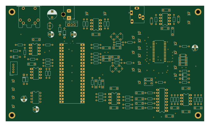 RP2040/RP2350
AS3397 proto DIP
167.6 × 97.5 mm138 parts2LMIT87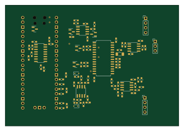 RP2040/RP2350
AS3397 eurorack 0603
92.2 × 64.2 mm110 parts2LMIT87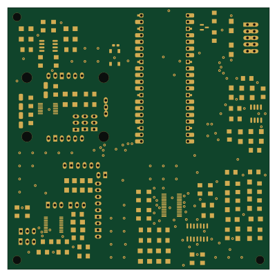 RP2040/RP2350
Carte FX 0
100 × 100 mm107 parts2LMIT87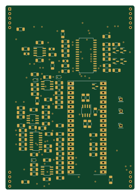 RP2040/RP2350
AS3397 proto SMS
70.5 × 100.2 mm105 parts2LMIT87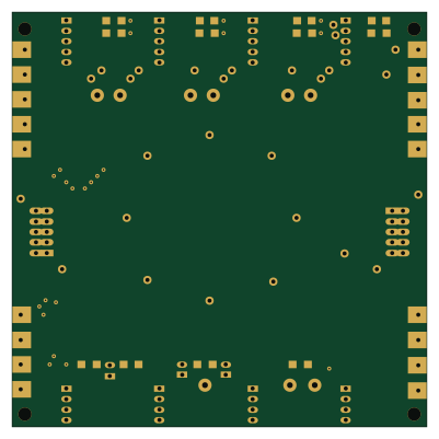
Carte BUS 1
100 × 100 mm52 parts2LMIT87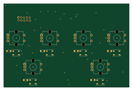
Poly UA controller 6enc 4sw
110.3 × 73.5 mm29 parts2LMIT87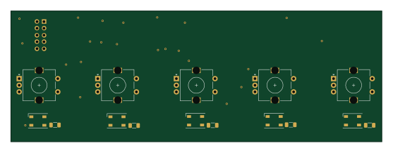
Poly UA controller 5enc 5sw
139.2 × 49.3 mm26 parts2LMIT87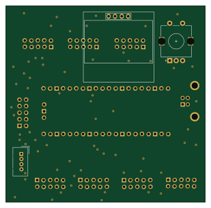 RP2040/RP2350
Main board
77.2 × 76.1 mm14 parts2LMIT87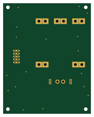
Power
76.6 × 96.6 mm3 parts2LMIT87
Similar boards
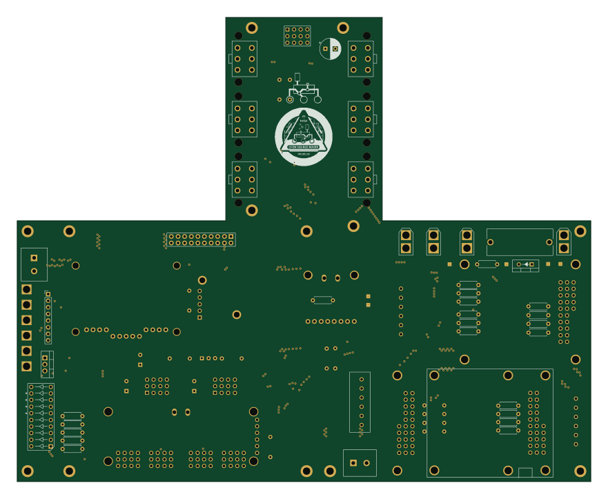 Raspberry Pi
Open source rover
nasa-jpl
220 × 178 mm144 parts2LApache-2.09.7k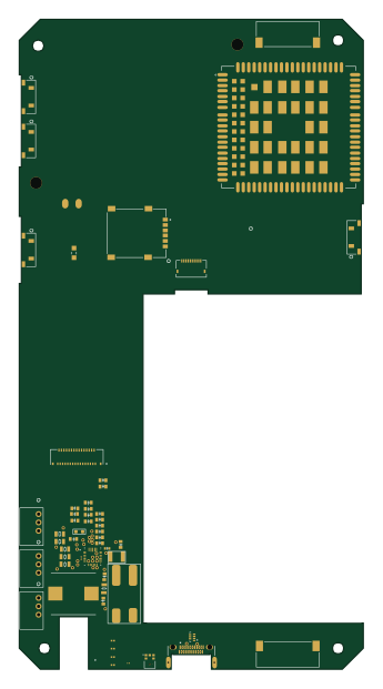 Raspberry Pi
SPIRIT
SPIRIT-org
82 × 155 mm130 parts6LCERN-OHL-S-2.01.3k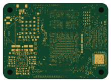 Raspberry Pi
CM5RevEng
schlae
55 × 40 mm417 parts10LNo license1.0k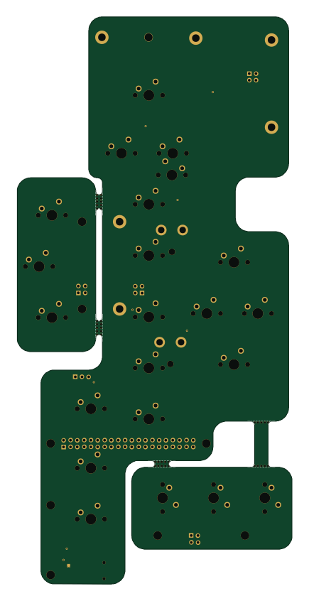 Raspberry Pi
Haxo hw
cardonabits
102.4 × 211.3 mm38 parts2LCustom license672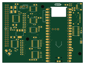 Raspberry Pi
PowerBook
BlueSCSI
74.5 × 56.3 mm78 parts2LGPL-3.0449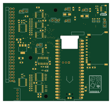 Raspberry Pi
Desktop 50 Pin TopConn
89.2 × 82.6 mm103 parts2LGPL-3.0449