
ESPBoosted

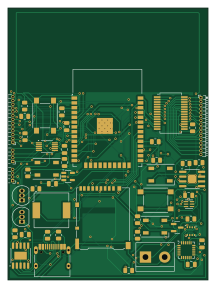
About the ESPBoosted PCB
ESPBoosted is an open source ESP32 PCB design by schoolllex, published on GitHub. It is a 2-layer board measuring 52.8 × 71.8 mm, with 51 components from 32 distinct parts.
Its main chip is the ESP32-WROOM-32E, from the ESP32 family. Other key parts include the CH340K, AP2112K-3.3TRG1, TP4056, ADS1115IDGSR and TSL25911FN. By type, the board carries 17 resistors, 9 ICs, 9 capacitors, 7 connectors, 3 transistors and 3 diodes.
It belongs with the power & battery, sensors and displays & leds designs in this gallery.
From the project
A custom, feature-rich ESP32-WROOM-32 development board featuring built-in environmental sensors, power management, and expansion interfaces. All project files, schematics, and manufacturing assets are included in the .zip archive within this repository.
A custom, feature-rich ESP32-WROOM-32 development board featuring built-in environmental sensors, power management, and expansion interfaces. All project files, schematics, and manufacturing assets are included in the .zip archive within this repository.
Core & Programming: ESP32-WROOM-32E module with onboard CH340K USB-to-UART bridge and automatic flash circuit. Power Management: AP2112K-3.3 LDO regulator, TP4056 LiPo battery charger, and power path management. Sensors & Peripherals: BME280 (Temperature, Humidity, Pressure) TSL25911FN (Digital Light Sensor) MPU-6050 (6-axis IMU /…
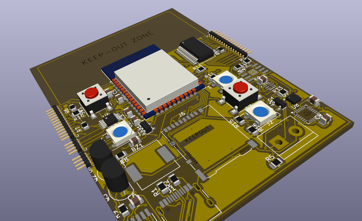
Main components on the ESPBoosted
ESPBoosted bill of materials (BOM)
51 components, 32 distinct parts — part numbers from the project's BOM.
| Qty | Part | Footprint | Refs |
|---|---|---|---|
| 1 | CH340K | SSOP-10-1EP_3.9x4.9mm_P1mm_EP2.1x3.3mm | U1 |
| 1 | ESP32-WROOM-32E TP4056 TOPPOWER(Nanjing Extension Microelectronics) | HSOP-8-1EP_3.9x4.9mm_P1.27mm_EP2.3x2.3mm_ThermalVias | U2 |
| 1 | AP2112K-3.3TRG1 AP2112K-3.3 | SOT-23-5 | U3 |
| 1 | TP4056 ESP32-WROOM-32E | ESP32-WROOM-32 | U4 |
| 1 | ADS1115IDGSR ADS1115IDGS | MSOP-10_3x3mm_P0.5mm | U6 |
| 1 | TSL25911FN BME280 | Bosch_LGA-8_2.5x2.5mm_P0.65mm_ClockwisePinNumbering | U7 |
| 1 | BME280 MPU-6050 | InvenSense_QFN-24_4x4mm_P0.5mm | U8 |
| 1 | MPU-6050 TSL25911FN | Broadcom_DFN-6_2x2mm_P0.65mm | U9 |
| 1 | MCP23017_SS | SSOP-28_5.3x10.2mm_P0.65mm | U10 |
| 1 | S8050 AO3401A | SOT-23 | Q1 |
| 1 | S8050 | TO-92_Inline | Q2 |
| 1 | AO3401A S8050 | TO-92_Inline | Q3 |
| 1 | HRO-TYPE-C-31-M-12 USB_C_Receptacle_USB2.0_16P | USB_C_Receptacle_HRO_TYPE-C-31-M-12 | J1 |
| 1 | SM04B-SRSS-TB Bat | TerminalBlock_bornier-2_P5.08mm | J2 |
| 1 | Conn_01x16_Socket | PinHeader_1x16_P1.00mm_Horizontal | J3 |
| 2 | Conn_01x04_Socket | PinHeader_1x04_P1.00mm_Horizontal | J4, J5 |
| 1 | DM3AT-SF-PEJM5 Micro_SD_Card | microSD_HC_Hirose_DM3AT-SF-PEJM5 | J6 |
| 1 | Conn_01x13_Socket | PinHeader_1x13_P1.00mm_Horizontal | J7 |
| 1 | CPT-9019S-SMT Buzzer | Buzzer_CUI_CPT-9019S-SMT | BZ1 |
| 2 | RESET_BTN | SW_SPST_PTS645 | SW1, SW2 |
Show 12 more
| Qty | Part | Footprint | Refs |
|---|---|---|---|
| 2 | LED | LED_WS2812B_PLCC4_5.0x5.0mm_P3.2mm | D1, D2 |
| 1 | SS14 WS2812B | LED_WS2812B_PLCC4_5.0x5.0mm_P3.2mm | D3 |
| 2 | 10uF | C_0805_2012Metric | C1, C3 |
| 6 | 100nF | C_0805_2012Metric | C2, C4, C5, C6, C8, C9 |
| 1 | 10nF | C_0805_2012Metric | C7 |
| 2 | 5.1k | R_0805_2012Metric | R1, R2 |
| 1 | 2k | R_0805_2012Metric | R3 |
| 2 | 1k | R_0805_2012Metric | R4, R12 |
| 3 | 100k | R_0805_2012Metric | R5, R6, R7 |
| 6 | 10K | R_0805_2012Metric | R8, R9, R10, R11, R13, R14 |
| 2 | 1.7k | R_0805_2012Metric | R15, R16 |
| 1 | 330R | R_0805_2012Metric | R33 |
ESPBoosted design files
The KiCad project lives in the schoolllex/ESPBoosted repository on GitHub; these links point at the commit this page was built from.
- LayoutESPBoosted.kicad_pcb
- SchematicESPBoosted.kicad_sch
- BOMbom.csv
ESPBoosted: common questions
What microcontroller does the ESPBoosted use?
The ESPBoosted is built around the ESP32-WROOM-32E, from the ESP32 family.
How big is the ESPBoosted PCB?
The ESPBoosted measures 52.8 × 71.8 mm, has 2 copper layers and is 1.6 mm thick.
How many components are on the ESPBoosted?
51 components, from 32 distinct parts, with part numbers taken from the project's own BOM. The full bill of materials is listed on this page.
Where can I download the ESPBoosted design files?
From the schoolllex/ESPBoosted repository on GitHub, which has the KiCad layout, the schematic and the BOM; the links under Design files point to each one.
Can I use the ESPBoosted design in my own project?
The repository has no license, so all rights stay with schoolllex. Use it as a reference, and ask the author before reusing the design.
Can I test firmware for the ESPBoosted without the hardware?
Yes. HardLabs builds a simulation of the board from its netlist and BOM, so you can run and debug ESP32 firmware against it before you order a PCB.
Similar boards
 ESP32
OSO-BOOK-B1
joeycastillo
85 × 115 mm65 parts2LCC-BY-SA-4.08.1k ESP32
Powertrain
byrantech
64 × 45.4 mm171 parts4LMIT4.3k ESP32
Badge
atopile
56.3 × 39 mm239 parts4LMIT4.0k ESP32
Esp32 minimal
36.2 × 26.8 mm20 parts2LMIT4.0k ESP32
Racer
StuckAtPrototype
36 × 50.2 mm70 parts4LApache-2.03.8k ESP32
Controller
29 × 74 mm58 parts4LApache-2.03.8k