
Dual CPU Base Board

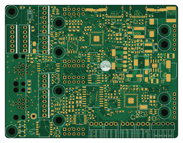
About the Dual CPU Base Board
Dual CPU Base Board is an open source RP2040/RP2350 PCB design by Twisted-Fields, published on GitHub under the Custom license license. It is a 4-layer board measuring 94.4 × 72.8 mm, with 247 components from 117 distinct parts.
Its main chip is the RP2040, from the RP2040/RP2350 family. Other key parts include the W25Q16JVSSIQ, LD1086DT33TR, TXS0101DCKR, TC7SH34FU,LJ(CT and ADC081S021CISD/NOPB. By type, the board carries 84 capacitors, 65 resistors, 30 ICs, 21 connectors, 21 diodes and 7 transistors.
It belongs with the robotics & motion designs in this gallery.
From the project
A dual channel brushless motor controller based on the RP2040 microcontroller, designed in Kicad.
The boards cost between $15 and $40 each depending on version and quantity.
Our dream is that you will fab your own boards, make changes, and share your work - giving this design life beyond our efforts.
Designed by Taylor Alexander for Twisted Fields, for the Acorn Precision Farming Rover.
Many thanks to Daniel Theobald. Without your financial support and encouragement this project would not have been possible.
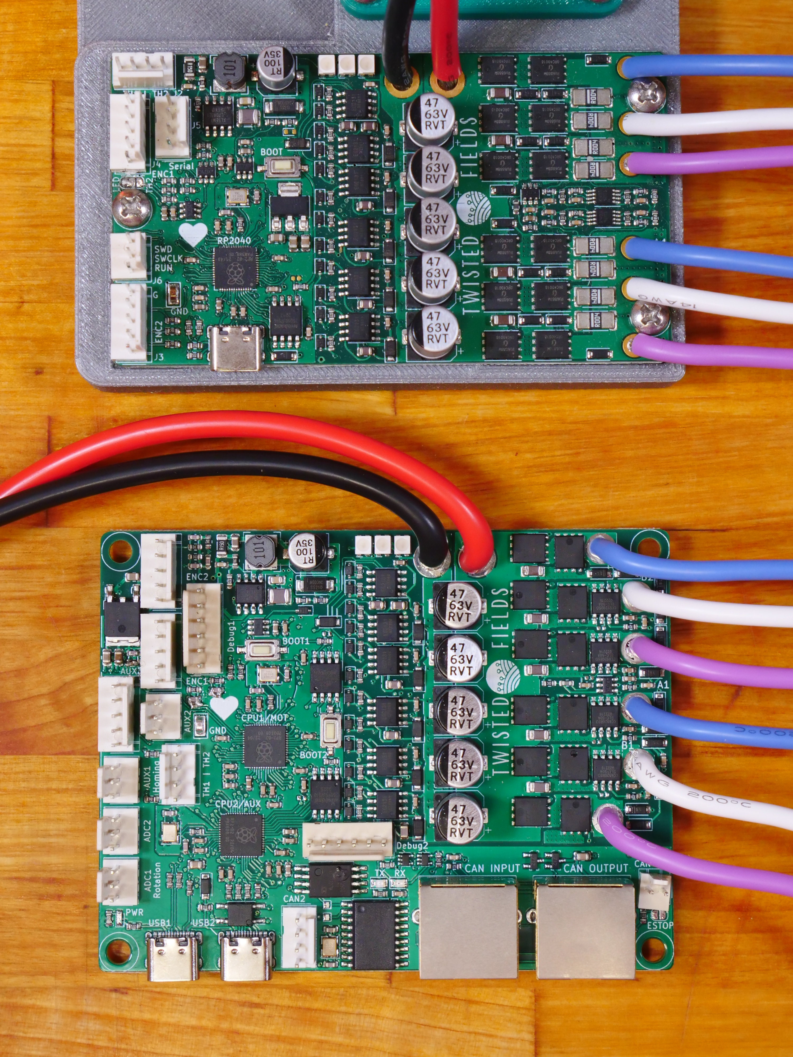
Main components on the Dual CPU Base Board
Dual CPU Base Board bill of materials (BOM)
247 components, 117 distinct parts — part numbers from the project's BOM.
| Qty | Part | Footprint | Refs |
|---|---|---|---|
| 1 | W25Q16JVSSIQ ~ | driver_module | U1 |
| 1 | LD1086DT33TR ~ | driver_module | U2 |
| 1 | RP2040 USBLC6-4SC6 | SOT-23-6 | U3 |
| 2 | TXS0101DCKR | SOT-363_SC-70-6 | U4, U10 |
| 3 | TC7SH34FU,LJ(CT SN74LVC1G07QDCKTQ1 | SOT-353_SC-70-5 | U6, U23, U25 |
| 2 | ADC081S021CISD/NOPB | SOT-23-6 | U9, U26 |
| 2 | TLV1117LV33DCYR | SOT-223-3_TabPin2 | U11, U32 |
| 2 | W25Q128JVSIQ | SOIC-8_5.23x5.23mm_P1.27mm | U12, U13 |
| 2 | RP2040 | RP2040-QFN-56 | U15, U19 |
| 1 | ~ | SOP-4_4.4x2.6mm_P1.27mm | U16 |
| 1 | CA-IS3052G | SOIC-8_7.5x5.85mm_P1.27mm | U17 |
| 1 | MCP2515-xSO | SOIC-18W_7.5x11.6mm_P1.27mm | U18 |
| 1 | ADS7822U | SOIC127P599X175-8N | U22 |
| 1 | MT2492 | SOT-23-6 | U24 |
| 2 | USBLC6-2P6 | SOT-666 | U27, U28 |
| 4 | USBLC6-4SC6 | SOT-23-6 | U29, U30, U31, U43 |
| 1 | TX4139 | SOIC-8-1EP_3.9x4.9mm_P1.27mm_EP2.29x3mm_ThermalVias | U33 |
| 1 | LTV-208 | SSOP-8_3.91x5.84x3.18mm_P1.27mm | U34 |
| 1 | PCA9557PWR | TSSOP-16_4.4x5mm_P0.65mm | U35 |
| 3 | AO7400-VB | SOT-323_SC-70 | Q1, Q2, Q11 |
Show 97 more
| Qty | Part | Footprint | Refs |
|---|---|---|---|
| 1 | AO7401 | SOT-23 | Q3 |
| 1 | LBSS139WT1G | SOT-323_SC-70 | Q4 |
| 2 | Q_NMOS_GSD | SOT-23 | Q7, Q8 |
| 1 | CRYSTAL_GND24 12MHz | Crystal_SMD_3225-4Pin_3.2x2.5mm | Y1 |
| 1 | 12MHz | Crystal_SMD_3225-4Pin_3.2x2.5mm | Y2 |
| 1 | 16MHz | Crystal_SMD_3225-4Pin_3.2x2.5mm | Y3 |
| 1 | USB_C_RECEPTACLE_USB2.0 CPU1 USB | USB_C_Receptacle_XKB_U262-16XN-4BVC11 | J1 |
| 1 | M12A-08PFFR-SF7003 CAN Input | M12A-08PFFR | J2 |
| 1 | CONN_01X06 Encoder 1 | Ckmtw-W-2510S06P_1x06_P2.54mm_Vertical | J3 |
| 1 | Encoder 2 | Ckmtw-W-2510S06P_1x06_P2.54mm_Vertical | J4 |
| 2 | Conn_01x06 | Ckmtw-W-2510S06P_1x06_P2.54mm_Vertical | J5, J12 |
| 1 | CPU2 USB | USB_C_Receptacle_XKB_U262-16XN-4BVC11 | J6 |
| 4 | Conn_02x05_Odd_Even | PinSocket_2x05_P2.54mm_Vertical | J7, J16, J19, J20 |
| 1 | Estop Conn | BOOMELE-2510-3A_1x03_P2.54mm_Vertical | J8 |
| 1 | ADC AUX 1 | CONN-TH_3P-P2.54_HCTL_HC-2510-3AW | J9 |
| 1 | AUX GPIO 1 | CONN-TH_3P-P2.54_HCTL_HC-2510-3AW | J10 |
| 1 | CAN2 PLUG | PINREX-744-81-04TW00 _1x04_P2.54mm_Vertical | J11 |
| 1 | ADC AUX 2 | CONN-TH_3P-P2.54_HCTL_HC-2510-3AW | J13 |
| 1 | AUX GPIO 2 | CONN-TH_3P-P2.54_HCTL_HC-2510-3AW | J14 |
| 1 | AUX Encoder | CONN-TH_5P-P2.54_HCTL_HC-2510-5AW | J15 |
| 1 | M12A-08PFFR-SF7003 CAN Output | M12A-08PFFR | J17 |
| 2 | Conn_01x06 | PinSocket_1x06_P2.54mm_Vertical | J18, J21 |
| 1 | 60V 1.5A hold polyfuse | Fuse_2920_7451Metric | F1 |
| 5 | SolderJumper_3_Open | SolderJumper-3_P1.3mm_Open_RoundedPad1.0x1.5mm | JP3, JP10, JP11, JP12, JP13 |
| 1 | SW_MEC_5G KT11B2SAM34LFS | KEY-SMD_KT11B2SAM34LFS | SW1 |
| 1 | CONFIG SWITCH | SW_DIP_SPSTx06_Slide_KingTek_DSHP06TS_W7.62mm_P1.27mm | SW3 |
| 1 | SW_DIP_x01 | SW-SMD_DSHP01TSGER | SW4 |
| 1 | KT11B2SAM34LFS | KEY-SMD_KT11B2SAM34LFS | SW5 |
| 1 | TestPoint | TestPoint_Loop_D2.60mm_Drill1.6mm_Beaded | TP2 |
| 1 | TestPoint | TestPoint_Keystone_5019_Minature | TP22 |
| 1 | WS2812B ESDCAN24-2BLY | SOT-23 | D1 |
| 1 | SMAJ5.0A/TR13 TVS 5V | D_SMA | D3 |
| 1 | SMAJ51A | D_SMC | D4 |
| 1 | SS310 | D_SMA | D27 |
| 4 | ESD5Z3V3 TVS 3.3V | D_SOD-523 | D28, D29, D30, D32 |
| 1 | 1N4148WS | D_SOD-323 | D31 |
| 3 | WS2812B | LED_WS2812_3528_3.5x2.8mm_P1.5mm | D33, D34, D35 |
| 2 | BAT54S | SOT-23 | D36, D44 |
| 2 | B5819W SL | D_SOD-123 | D37, D43 |
| 1 | LED_GREEN | LED_0805_2012Metric | D38 |
| 1 | LED_YELLOW | LED_0805_2012Metric | D39 |
| 1 | ESDCAN24-2BLY | SOT-23 | D40 |
| 1 | LTST-C150KRKT LED_RED | LED_0603_1608Metric | D41 |
| 1 | 10V Zener | D_SOD-123 | D45 |
| 1 | 1.6Ω ±25% 1kΩ@100MHz | L_0603_1608Metric | FB2 |
| 1 | 68uH 1A | L_Sunlord_SWPA6045S | L1 |
| 1 | 10uH | L_Sunlord_SWPA5040S | L2 |
| 1 | 47uH | L_Chilisin_BMRB00060612 | L3 |
| 2 | 100N 4.7uF 35V | C_0603_1608Metric | C1, C8 |
| 2 | 10U 4.7uF 100V | C_1210_3225Metric | C2, C3 |
| 1 | 10U 100n | C_0603_1608Metric | C4 |
| 2 | 20P ~ | C_0805_2012Metric | C5, C6 |
| 1 | 10U ~ | C_0805_2012Metric | C7 |
| 2 | 100N ~ | C_0805_2012Metric | C9, C11 |
| 1 | ~ | C_0805_2012Metric | C10 |
| 5 | 10u | C_0805_2012Metric | C12, C24, C29, C86, C110 |
| 1 | 100N 10u | C_0805_2012Metric | C13 |
| 1 | 100N 10uF 25v | C_0603_1608Metric | C14 |
| 1 | 100N 2.2u | C_0603_1608Metric | C15 |
| 1 | 100N 1u | C_0603_1608Metric | C18 |
| 4 | 20p | C_0603_1608Metric | C19, C27, C28, C42 |
| 10 | 1u | C_0603_1608Metric | C20, C32, C34, C35, C53, C54, C121, C122 +2 |
| 26 | 100n | C_0603_1608Metric | C21, C22, C30, C31, C33, C36, C37, C38 +18 |
| 7 | 47p | C_0603_1608Metric | C23, C60, C61, C62, C63, C64, C113 |
| 2 | 18p | C_0603_1608Metric | C57, C58 |
| 6 | 22nF | C_0805_2012Metric | C87, C88, C89, C90, C91, C92 |
| 2 | 22uF 25V | C_0805_2012Metric | C94, C96 |
| 1 | 47uF 10v | C_0805_2012Metric | C95 |
| 1 | 22pF | C_0603_1608Metric | C97 |
| 1 | 22nF | C_0603_1608Metric | C98 |
| 1 | 4.7uF 100V | C_1210_3225Metric | C111 |
| 1 | 100nF 100V | C_0805_2012Metric | C112 |
| 1 | 220uF 25V | CP_Elec_6.3x7.7 | C115 |
| 1 | 47uF 63V solid | CP_Elec_8x10.5 | C120 |
| 2 | 1.1K ~ | R_0805_2012Metric | R1, R5 |
| 3 | 50k 0.1% | R_0603_1608Metric | R2, R23, R64 |
| 2 | 5.1K ~ | R_0805_2012Metric | R3, R4 |
| 2 | ~ | R_0805_2012Metric | R6, R7 |
| 19 | 10k | R_0603_1608Metric | R8, R11, R12, R13, R14, R17, R18, R19 +11 |
| 4 | 120R | R_0603_1608Metric | R9, R48, R75, R100 |
| 1 | 510R | R_0603_1608Metric | R10 |
| 1 | 110k 0.1% | R_0603_1608Metric | R15 |
| 1 | 15k 0.1% | R_0603_1608Metric | R16 |
| 2 | 47k | R_0603_1608Metric | R20, R21 |
| 1 | 500k | R_0603_1608Metric | R22 |
| 8 | 5.1k | R_0603_1608Metric | R40, R43, R44, R46, R49, R62, R63, R76 |
| 4 | 1.1k | R_0603_1608Metric | R41, R47, R52, R66 |
| 5 | 27R | R_0603_1608Metric | R60, R61, R67, R70, R71 |
| 1 | 5.1k 0.1% | R_0603_1608Metric | R65 |
| 1 | 56R | R_0603_1608Metric | R68 |
| 1 | 82R | R_0603_1608Metric | R77 |
| 1 | 30mΩ 5% | R_0603_1608Metric | R95 |
| 1 | 300k | R_0603_1608Metric | R96 |
| 1 | 21.5k | R_0603_1608Metric | R97 |
| 1 | 10Ω | R_0603_1608Metric | R98 |
| 1 | 10.2R | R_0603_1608Metric | R99 |
| 2 | 100k | R_0603_1608Metric | R103, R106 |
Dual CPU Base Board design files
The KiCad project lives in the Twisted-Fields/rp2040-motor-controller repository on GitHub; these links point at the commit this page was built from.
Dual CPU Base Board: common questions
What microcontroller does the Dual CPU Base Board use?
The Dual CPU Base Board is built around the RP2040, from the RP2040/RP2350 family.
How big is the Dual CPU Base Board?
The Dual CPU Base Board measures 94.4 × 72.8 mm, has 4 copper layers and is 1.609 mm thick.
How many components are on the Dual CPU Base Board?
247 components, from 117 distinct parts, with part numbers taken from the project's own BOM. The full bill of materials is listed on this page.
Where can I download the Dual CPU Base Board design files?
From the Twisted-Fields/rp2040-motor-controller repository on GitHub, which has the KiCad layout, the schematic and the BOM; the links under Design files point to each one.
Can I use the Dual CPU Base Board design in my own project?
It is published under Custom license, which limits how it may be reused; read the license before building on it.
Can I test firmware for the Dual CPU Base Board without the hardware?
Yes. HardLabs builds a simulation of the board from its netlist and BOM, so you can run and debug RP2040/RP2350 firmware against it before you order a PCB.
More boards in rp2040-motor-controller
 RP2040/RP2350
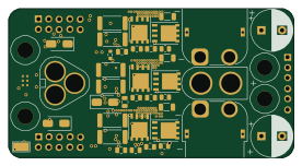
Driver Module
68.8 × 36 mm107 parts4LCustom license417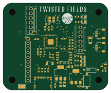 RP2040/RP2350
RP2040 Debugger
57 × 47.5 mm60 parts4LCustom license417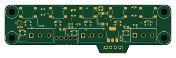 RP2040/RP2350
User interface
90 × 26 mm37 parts4LCustom license417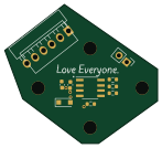
Rp2040 encoder
36.7 × 33.3 mm10 parts2LCustom license417
Similar boards
 RP2040/RP2350
Open Book Abridged Edition
joeycastillo
85 × 115 mm29 parts2LCC-BY-SA-4.08.1k RP2040/RP2350
Corne
foostan
277.2 × 107.5 mm164 parts2LCC-BY-4.07.7k RP2040/RP2350
Corne
277.2 × 107.5 mm164 parts2LCC-BY-4.07.7k RP2040/RP2350
Msa
Mentra-Community
47.8 × 9.4 mm53 parts2LMIT1.2k RP2040/RP2350
Open Source Smart Glasses
93 × 10.5 mm80 parts4LMIT1.2k RP2040/RP2350
MSA
30.5 × 138 mm61 parts2LMIT1.2k