
Processor attempt 1

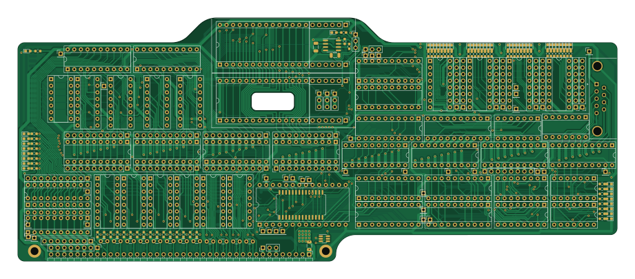
About the Processor attempt 1 PCB
Processor attempt 1 is an open source PCB design by ethanjamesauto, published on GitHub. It is a 2-layer board measuring 229.9 × 93.3 mm, with 365 components from 51 distinct parts.
Other key parts include the NE555D, 74LS161, 74LS574, 28C256 and 74LS245. By type, the board carries 142 resistors, 82 diodes, 65 connectors, 49 ICs, 14 capacitors and 12 transistors.
From the project
CPU card Protoboard card This card contains an onboard clock generator, address and data registers/buffers, and a protoboard area for testing designs. Bus interface modeling
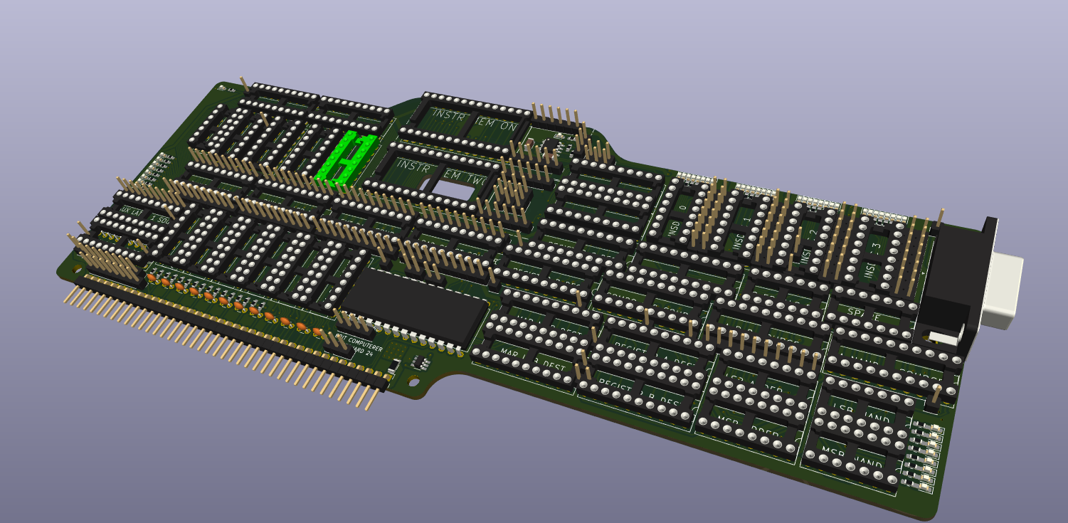
Main components on the Processor attempt 1
Processor attempt 1 bill of materials (BOM)
365 components, 51 distinct parts.
| Qty | Part | Footprint | Refs |
|---|---|---|---|
| 1 | NE555D | SOIC-8_3.9x4.9mm_P1.27mm | U1 |
| 4 | 74LS161 | DIP-16_W7.62mm_Socket | U2, U3, U4, U5 |
| 9 | 74LS574 | DIP-20_W7.62mm_Socket | U6, U7, U25, U26, U27, U44, U45, U47 +1 |
| 2 | 28C256 | DIP-28_W15.24mm_Socket | U18, U19 |
| 8 | 74LS245 | DIP-20_W7.62mm_Socket | U21, U23, U29, U30, U31, U48, U49, U50 |
| 3 | 74LS273 | DIP-20_W7.62mm_Socket | U24, U40, U41 |
| 1 | HM62256BLP | DIP-28_W15.24mm | U28 |
| 2 | 74LS283 | DIP-16_W7.62mm_Socket | U32, U39 |
| 6 | ~ | DIP-16_W7.62mm_Socket | U33, U34, U35, U36, U37, U38 |
| 2 | 74LS04 | DIP-14_W7.62mm_Socket | U42, U56 |
| 1 | 74HC688 | DIP-20_W7.62mm_Socket | U43 |
| 1 | HM62256BLP | SOIC-28W_7.5x18.7mm_P1.27mm | U46 |
| 1 | 74LS161 | SOIC-16_3.9x9.9mm_P1.27mm | U51 |
| 2 | 74LS00 | DIP-14_W7.62mm_Socket | U52, U53 |
| 1 | 74LS30 | DIP-14_W7.62mm_Socket | U55 |
| 4 | 74LS138 | DIP-16_W7.62mm_Socket | U57, U58, U59, U60 |
| 1 | 74LVC1G08 | SOT-23-6_Handsoldering | U61 |
| 12 | FDG1024NZ | SOT-23-6_Handsoldering | Q1, Q2, Q3, Q4, Q5, Q6, Q7, Q8 +4 |
| 6 | Conn_01x03_Pin | PinHeader_1x03_P2.54mm_Vertical | J1, J31, J32, J33, J34, J69 |
| 1 | Conn_01x40_Pin | PinHeader_1x40_P2.54mm_Horizontal | J3 |
Show 31 more
| Qty | Part | Footprint | Refs |
|---|---|---|---|
| 10 | Conn_01x08_Pin | PinHeader_1x08_P2.54mm_Vertical | J4, J20, J22, J23, J24, J25, J26, J27 +2 |
| 9 | Conn_01x10_Pin | PinHeader_1x10_P2.54mm_Vertical | J7, J8, J9, J10, J11, J12, J13, J18 +1 |
| 4 | Conn_01x06_Pin | PinHeader_1x06_P2.54mm_Vertical | J14, J15, J16, J17 |
| 4 | Conn_01x01_Pin | PinHeader_1x01_P2.54mm_Vertical | J30, J35, J40, J42 |
| 30 | J | PinHeader_1x01_P2.54mm_Vertical | J36, J41, J43, J44, J45, J46, J47, J48 +22 |
| 1 | Clock_Aux_Latch_0 | PinHeader_1x01_P2.54mm_Vertical | J39 |
| 1 | 1 | R_1206_3216Metric | 5V_rsns1 |
| 37 | A0 | LED_0603_1608Metric_Pad1.05x0.95mm_HandSolder | D1, D17, D25, D33, D41, D49, D50, D51 +29 |
| 5 | A1 | LED_0603_1608Metric_Pad1.05x0.95mm_HandSolder | D2, D18, D26, D34, D42 |
| 5 | A2 | LED_0603_1608Metric_Pad1.05x0.95mm_HandSolder | D3, D19, D27, D35, D43 |
| 5 | A3 | LED_0603_1608Metric_Pad1.05x0.95mm_HandSolder | D4, D20, D28, D36, D44 |
| 6 | A4 | LED_0603_1608Metric_Pad1.05x0.95mm_HandSolder | D5, D21, D29, D37, D45, D82 |
| 5 | A5 | LED_0603_1608Metric_Pad1.05x0.95mm_HandSolder | D6, D22, D30, D38, D46 |
| 5 | A6 | LED_0603_1608Metric_Pad1.05x0.95mm_HandSolder | D7, D23, D31, D39, D47 |
| 5 | A7 | LED_0603_1608Metric_Pad1.05x0.95mm_HandSolder | D8, D24, D32, D40, D48 |
| 1 | A8 | LED_0603_1608Metric_Pad1.05x0.95mm_HandSolder | D9 |
| 1 | A9 | LED_0603_1608Metric_Pad1.05x0.95mm_HandSolder | D10 |
| 1 | A10 | LED_0603_1608Metric_Pad1.05x0.95mm_HandSolder | D11 |
| 1 | A11 | LED_0603_1608Metric_Pad1.05x0.95mm_HandSolder | D12 |
| 1 | A12 | LED_0603_1608Metric_Pad1.05x0.95mm_HandSolder | D13 |
| 1 | A13 | LED_0603_1608Metric_Pad1.05x0.95mm_HandSolder | D14 |
| 1 | A14 | LED_0603_1608Metric_Pad1.05x0.95mm_HandSolder | D15 |
| 1 | A15 | LED_0603_1608Metric_Pad1.05x0.95mm_HandSolder | D16 |
| 1 | 5V_RAW | LED_0603_1608Metric_Pad1.05x0.95mm_HandSolder | D81 |
| 2 | C | C_1206_3216Metric | C1, C2 |
| 12 | 100nF | C_Disc_D3.0mm_W1.6mm_P2.50mm | C3, C4, C5, C6, C7, C9, C10, C11 +4 |
| 4 | R | R_0603_1608Metric_Pad0.98x0.95mm_HandSolder | R1, R2, R141, R142 |
| 28 | 10k | R_0603_1608Metric_Pad0.98x0.95mm_HandSolder | R3, R4, R6, R7, R11, R12, R13, R14 +20 |
| 24 | 1k | R_0603_1608Metric_Pad0.98x0.95mm_HandSolder | R5, R8, R9, R10, R15, R16, R17, R18 +16 |
| 4 | 0 | R_0603_1608Metric_Pad0.98x0.95mm_HandSolder | R103, R104, R105, R106 |
| 82 | 470 | R_0603_1608Metric_Pad0.98x0.95mm_HandSolder | r51, r52, r53, r54, r55, r56, r57, r58 +74 |
Processor attempt 1 design files
The KiCad project lives in the ethanjamesauto/modular_8bit_computer repository on GitHub; these links point at the commit this page was built from.
Processor attempt 1: common questions
How big is the Processor attempt 1 PCB?
The Processor attempt 1 measures 229.9 × 93.3 mm, has 2 copper layers and is 1.6 mm thick.
How many components are on the Processor attempt 1?
365 components, from 51 distinct parts. The full bill of materials is listed on this page.
Where can I download the Processor attempt 1 design files?
From the ethanjamesauto/modular_8bit_computer repository on GitHub, which has the KiCad layout and the schematic; the links under Design files point to each one.
Can I use the Processor attempt 1 design in my own project?
The repository has no license, so all rights stay with ethanjamesauto. Use it as a reference, and ask the author before reusing the design.
More boards in modular_8bit_computer
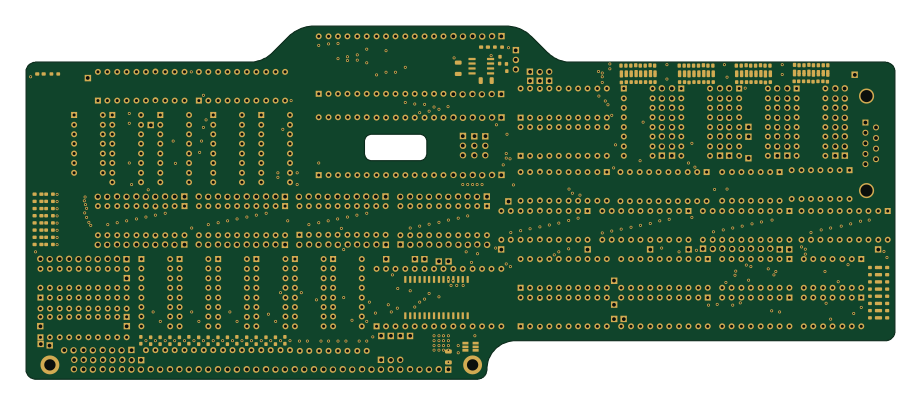
Huhhhh I didnt save
229.9 × 93.3 mm365 parts2LNo license1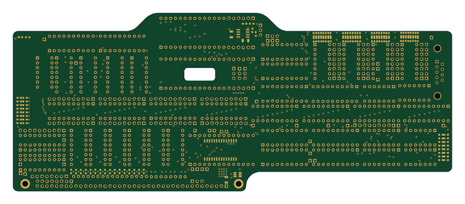
Processor attempt 3
229.9 × 93.3 mm365 parts2LNo license1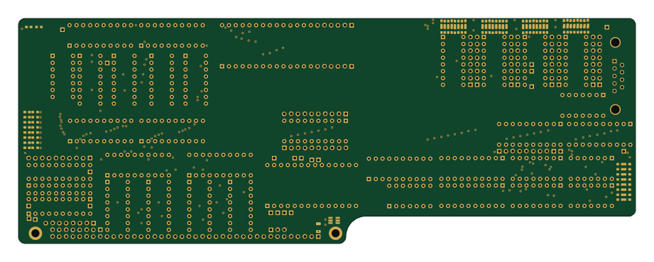
Processor attempt 4
229.9 × 83.8 mm291 parts2LNo license1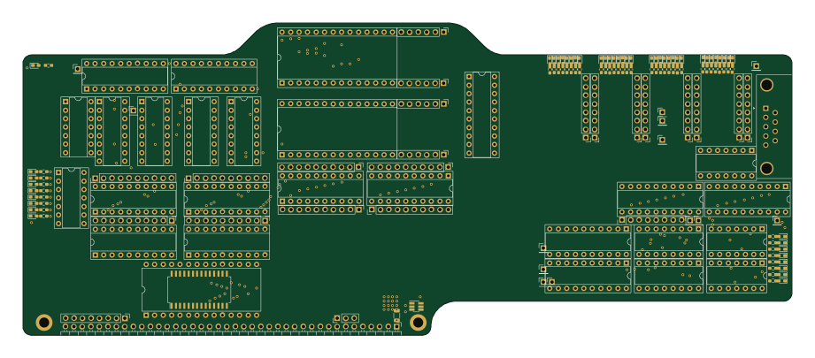
Processor attempt 2
229.9 × 93.3 mm272 parts2LNo license1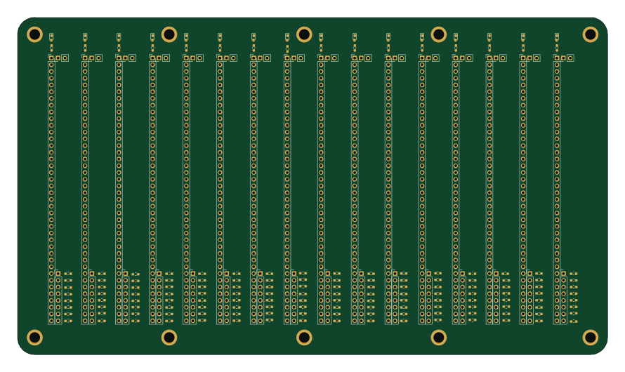
Motherboard
222.3 × 127 mm208 parts2LNo license1
Fish
0.7 × 0.3 mm162 parts2LNo license1
Eddie bldc
48.3 × 48.3 mm63 parts2LNo license1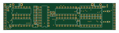
8 bit logic analyzer
104.1 × 25.4 mm60 parts2LNo license1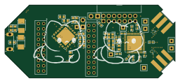
PCB PCB OpenSuperHetv6
64.1 × 27.6 mm57 parts2LNo license1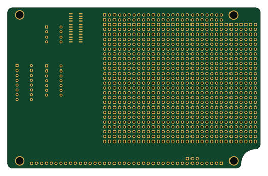
93c46a type
132.1 × 83.8 mm39 parts2LNo license1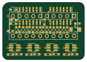
74ls245 high current attempt 2
30.5 × 21.6 mm37 parts2LNo license1