
CortexPC

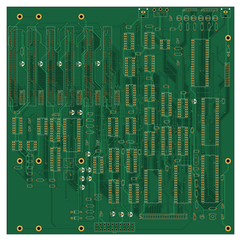
About the CortexPC PCB
CortexPC is an open source AVR/Arduino PCB design by danwerner21, published on GitHub. It is a 2-layer board measuring 244 × 244 mm, with 155 components from 84 distinct parts.
Its main chip is the ATtiny85-20P, from the AVR/Arduino family. Other key parts include the 74LS07, TMS9995-DIP_1, 74LS04, 74LS74 and 74LS112. By type, the board carries 53 capacitors, 31 ICs, 29 connectors, 23 resistors, 9 diodes and 5 jumpers.
It belongs with the audio designs in this gallery.
From the project
Powertran Cortex clone. PC formfactor, based on Stuart Conner's MiniCortex
This is an ATX format implimentation of the Mini-Cortex system by Paul Ruizendaal and Stuart Conner. The Mini-Cortex system is a further development of a TMS 9995 breadboard project to produce a system similar to a Powertran Cortex, but using more modern components. The system is based around a TMS 9995 running at 3 MHz, with 32K byte EEPROM, and will use 512K bytes of RAM accessed through a memory mapper. An on-board serial port and IDE interface exists on the card. There is also provisions for a TMS9918 clone, a keyboard and some expansion slots -- these are not totally supported by the…
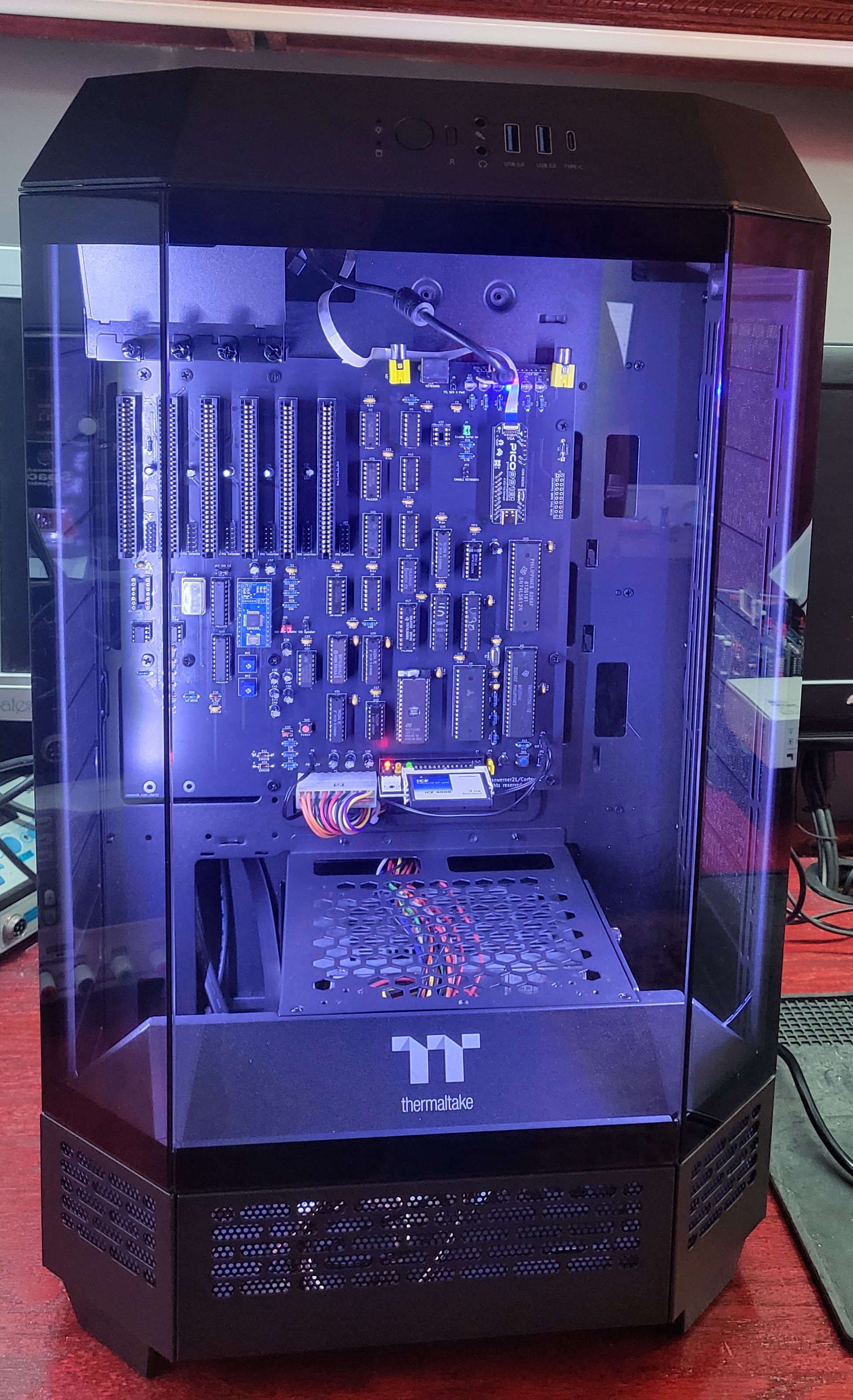
Main components on the CortexPC
CortexPC bill of materials (BOM)
155 components, 84 distinct parts.
| Qty | Part | Footprint | Refs |
|---|---|---|---|
| 1 | 74LS07 | STD_DDW_DIP14 | U2 |
| 1 | TMS9995-DIP_1 | STD_DDW_DIP40 | U3 |
| 1 | 74LS04 | STD_DDW_DIP14 | U4 |
| 2 | 74LS74 | STD_DDW_DIP14 | U5, U27 |
| 1 | 74LS112 | STD_DDW_DIP16 | U6 |
| 1 | SN76489 | STD_DDW_DIP16 | U7 |
| 1 | DS1233 | STD_DDW_TO92 | U8 |
| 1 | SRAM_512K | STD_DDW_DIP32 | U9 |
| 1 | TMS9918 EMU | STD_DDW_DIP40 | U10 |
| 2 | GAL22V10 | STD_DDW_DIP24_Skinny | U11, U30 |
| 2 | 74LS32 | STD_DDW_DIP14 | U12, U13 |
| 1 | 74LS138 | STD_DDW_DIP16 | U15 |
| 1 | 6581 | STD_DDW_DIP28 | U16 |
| 1 | 74LS688 | STD_DDW_DIP20 | U17 |
| 1 | 27C256 | STD_DDW_DIP28 | U18 |
| 2 | 74LS374 | STD_DDW_DIP20 | U19, U20 |
| 1 | TMS9902A | STD_DDW_DIP18 | U21 |
| 1 | 74LS259 | STD_DDW_DIP16 | U22 |
| 1 | 74LS612-DIP | STD_DDW_DIP40 | U23 |
| 2 | LM386 | STD_DDW_DIP8 | U24, U32 |
Show 64 more
| Qty | Part | Footprint | Refs |
|---|---|---|---|
| 1 | 74LS245 | STD_DDW_DIP20 | U25 |
| 1 | 74HCT14 | STD_DDW_DIP14 | U26 |
| 3 | 74LS244 | STD_DDW_DIP20 | U28, U29, U31 |
| 1 | ATtiny85-20P | STD_DDW_DIP8 | U33 |
| 1 | 12MHz | STD_DDW_XTAL | Y1 |
| 1 | F18A TANG NANO Connector | STD_DDW_PinHeader_2x10 | J1 |
| 6 | IRQ Selection | STD_DDW_PINHEAD_V_2x06 | J2, J8, J11, J13, J15, J17 |
| 6 | Bus_I_not_SA_8bit | BUSPC_HOST | J3, J10, J12, J14, J16, J18 |
| 1 | Enable Serial Int | STD_DDW_PINHEAD_V_1x02 | J4 |
| 1 | TTL SERIAL 0 | STD_DDW_PINHEAD_V_1x06 | J5 |
| 1 | TTL SER 0 PWR | STD_DDW_PINHEAD_V_1x02 | J6 |
| 1 | USER OUT | STD_DDW_PINHEAD_V_1x07 | J7 |
| 1 | AUDIO OUT | CUI_RCJ-047 | J9 |
| 1 | KEYBOARD | PS2_DIN | J19 |
| 1 | SID Speaker | STD_DDW_PINHEAD_V_1x02 | J20 |
| 1 | SID AMP Enable | STD_DDW_PINHEAD_V_1x02 | J21 |
| 1 | SN76489 AMP Enable | STD_DDW_PINHEAD_V_1x02 | J22 |
| 1 | SN76489 Speaker | STD_DDW_PINHEAD_V_1x02 | J23 |
| 1 | SID OUT | CUI_RCJ-047 | J24 |
| 1 | 14.31818 MHz CLK | STD_DDW_DIP14 | P1 |
| 1 | 1 MHz CLK | STD_DDW_DIP14 | P3 |
| 1 | 8 BIT IDE (CF) | STD_DDW_PINHEAD_V_2x20 | P4 |
| 1 | CONN_10X2 | ATXConnector | P5 |
| 1 | POWER_SW | STD_DDW_PINHEAD_V_1x02 | P6 |
| 1 | JUMPER | STD_DDW_PINHEAD_V_1x02 | JP1 |
| 1 | ENABLE KEYBOARD | STD_DDW_PINHEAD_V_1x02 | JP2 |
| 1 | SID CS | STD_DDW_PINHEAD_V_1x03 | JP3 |
| 1 | EXT IDE LED | STD_DDW_PINHEAD_V_1x02 | JP4 |
| 1 | IDE PWR | STD_DDW_PINHEAD_V_1x03 | JP5 |
| 2 | 10K | Potentiometer_Bourns_3386F_Vertical | RV1, RV2 |
| 1 | RESET | STD_DDW_TACTSW | SW1 |
| 1 | POWER | STD_DDW_TACTSW | SW2 |
| 1 | PWR | STD_DDW_LED5 | D1 |
| 1 | IDLE | STD_DDW_LED5 | D2 |
| 1 | MAP | STD_DDW_LED5 | D3 |
| 1 | 1N5817 | STD_DDW_DIODE | D5 |
| 1 | IDE ACT | STD_DDW_LED5 | D6 |
| 1 | Tx | STD_DDW_LED5 | D8 |
| 1 | Rx | STD_DDW_LED5 | D9 |
| 2 | 1N4148 | STD_DDW_DIODE | D10, D11 |
| 23 | 0.1u | STD_DDW_CAP | C1, C2, C3, C4, C5, C6, C7, C8 +15 |
| 4 | 10u | STD_DDW_PCAP | C18, C20, C22, C24 |
| 1 | 22u | STD_DDW_PCAP | C26 |
| 1 | 47uF | STD_DDW_PCAP | C28 |
| 1 | 1uF | STD_DDW_PCAP | C30 |
| 5 | 10uf | STD_DDW_PCAP | C31, C39, C43, C49, C58 |
| 2 | 0.1 uF | STD_DDW_CAP | C32, C37 |
| 1 | 0.01 uF | STD_DDW_CAP | C33 |
| 1 | 100µF | STD_DDW_PCAP | C34 |
| 1 | 0.1µF | STD_DDW_CAP | C35 |
| 1 | 4.7pF | STD_DDW_CAP | C36 |
| 1 | 0.22uf | STD_DDW_PCAP | C38 |
| 2 | 15pf | STD_DDW_CAP | C40, C41 |
| 2 | 2200pf | STD_DDW_CAP | C42, C46 |
| 2 | 470pf | STD_DDW_CAP | C44, C45 |
| 2 | 0.047uf | STD_DDW_CAP | C47, C56 |
| 2 | 220uf | STD_DDW_PCAP | C48, C57 |
| 1 | 0.47uf | STD_DDW_PCAP | C50 |
| 8 | 470 | STD_DDW_RESISTOR | R1, R3, R6, R7, R11, R12, R13, R17 |
| 9 | 10k | STD_DDW_RESISTOR | R2, R4, R8, R14, R16, R18, R28, R29 +1 |
| 1 | 1000 | STD_DDW_RESISTOR | R5 |
| 1 | 10Ω | STD_DDW_RESISTOR | R9 |
| 2 | 10 ohms | STD_DDW_RESISTOR | R15, R24 |
| 2 | 4.7K | STD_DDW_RESISTOR | R26, R27 |
CortexPC design files
The KiCad project lives in the danwerner21/CortexPC repository on GitHub; these links point at the commit this page was built from.
- LayoutHardware/CortexPC.kicad_pcb
- SchematicHardware/CortexPC.kicad_sch
CortexPC: common questions
What microcontroller does the CortexPC use?
The CortexPC is built around the ATtiny85-20P, from the AVR/Arduino family.
How big is the CortexPC PCB?
The CortexPC measures 244 × 244 mm, has 2 copper layers and is 1.6 mm thick.
How many components are on the CortexPC?
155 components, from 84 distinct parts. The full bill of materials is listed on this page.
Where can I download the CortexPC design files?
From the danwerner21/CortexPC repository on GitHub, which has the KiCad layout and the schematic; the links under Design files point to each one.
Can I use the CortexPC design in my own project?
The repository has no license, so all rights stay with danwerner21. Use it as a reference, and ask the author before reusing the design.
Can I test firmware for the CortexPC without the hardware?
Yes. HardLabs builds a simulation of the board from its netlist and BOM, so you can run and debug AVR/Arduino firmware against it before you order a PCB.
Similar boards
 AVR/Arduino
Magspoof
samyk
35 × 29 mm11 parts2LNo license4.2k AVR/Arduino
Redox keyboard
mattdibi
162.2 × 126.5 mm77 parts2LMIT2.0k AVR/Arduino
Labrador
espotek-org
36.8 × 34.7 mm75 parts2LNo license1.2k AVR/Arduino
V4
stuartpittaway
30 × 50 mm38 parts2LCC-BY-NC-4.01.1k AVR/Arduino
ModuleV450
30 × 61.4 mm39 parts2LCC-BY-NC-4.01.1k AVR/Arduino
Discipline
coseyfannitutti
304.9 × 122.8 mm170 parts2LCC-BY-NC-4.01.0k