
FujiNet-INTV-Rev0

About the FujiNet-INTV-Rev0 PCB
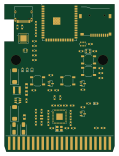
FujiNet-INTV-Rev0 is an open source ESP32 PCB design by FujiNetWIFI, published on GitHub under the CERN-OHL-S-2.0 license. It is a 4-layer board measuring 58.2 × 78 mm, with 77 components from 37 distinct parts.
Its main chip is the ESP32-S3-WROOM-1-N16R8, from the ESP32 family. Other key parts include the RP2354A, CP2102N-A02-GQFN28R, UMH3N and AP63203WU-7. By type, the board carries 33 capacitors, 19 resistors, 7 diodes, 5 ICs, 4 switches and 3 transistors.
It belongs with the iot & wireless designs in this gallery.
From the project
Schematics and design files for FujiNet hardware
All-in-one Intellivision FujiNet cartridge: one board carrying both halves of the INTV FujiNet stack —
- RP2354A (RP2350A + 2 MB stacked flash, QFN-60) running the Minty-derived cartridge firmware from fujinet-firmware/pico/intellivision/firmware, built with -DPICOBOARD=fujicard. It emulates the cartridge on the CP-1610 bus (GPIO0–15 = AD0–AD15 wired directly to the 5 V cart edge — RP2350-family pads are 5 V-tolerant with IOVDD = 3.3 V) and exposes the FujiNet mailbox at $9C00-$9F3F. - ESP32-S3-WROOM-1-N16R8 running the fujiversal-intv build of fujinet-firmware (./build.sh -e…
Main components on the FujiNet-INTV-Rev0
FujiNet-INTV-Rev0 bill of materials (BOM)
77 components, 37 distinct parts — part numbers from the project's BOM.
| Qty | Part | Footprint | Refs |
|---|---|---|---|
| 1 | RP2354A | QFN-60-1EP_7x7mm_P0.4mm_EP3.4x3.4mm | U1 |
| 1 | ESP32-S3-WROOM-1-N16R8 | ESP32-S3-WROOM-1 | U2 |
| 1 | CP2102N-A02-GQFN28R CP2102N-A02-GQFN28 | QFN-28-1EP_5x5mm_P0.5mm_EP3.35x3.35mm | U3 |
| 1 | UMH3N | SOT-363_SC-70-6 | U4 |
| 1 | AP63203WU-7 AP63203WU | TSOT-23-6 | U5 |
| 3 | BC847 | SOT-23 | Q1, Q2, Q3 |
| 1 | ABM8-272-T3 12MHz | Crystal_SMD_3225-4Pin_3.2x2.5mm | Y1 |
| 1 | card edge, 2x22, 2.54mm INTV_Cart_Edge_44 | INTV_Cart_Edge_44 | J1 |
| 1 | SUNTECH ST-TF-003A microSD | microSD_SUNTECH_ST-TF-003A | J2 |
| 1 | HRO TYPE-C-31-M-12 USB-C | USB_C_Receptacle_HRO_TYPE-C-31-M-12 | J3 |
| 1 | RUN | SW_SPST_TL3342 | SW1 |
| 1 | BOOTSEL | SW_SPST_TL3342 | SW2 |
| 1 | RESET | SW_SPST_TL3342 | SW3 |
| 1 | BOOT | SW_SPST_TL3342 | SW4 |
| 1 | LED | LED_0603_1608Metric | D1 |
| 1 | WS2812B-2020 | LED_WS2812B-2020_PLCC4_2.0x2.0mm | D2 |
| 3 | ESD5Z5.0T1G | D_SOD-523 | D3, D4, D5 |
| 2 | SS34 | D_SMA | D6, D7 |
| 1 | AOTA-B201610S3R3-101-T 3.3uH | L_2016Metric | L1 |
| 1 | 6.8uH >=2.5A shielded 4030 6.8uH | L_Sunlord_SWPA4030S | L2 |
Show 17 more
| Qty | Part | Footprint | Refs |
|---|---|---|---|
| 2 | 15pF | C_0603_1608Metric | C1, C2 |
| 16 | 100nF | C_0603_1608Metric | C3, C4, C5, C6, C7, C8, C9, C10 +8 |
| 4 | 4.7uF | C_0603_1608Metric | C13, C14, C15, C27 |
| 3 | 10uF | C_0603_1608Metric | C16, C17, C20 |
| 3 | 1uF | C_0603_1608Metric | C18, C21, C24 |
| 1 | 6.3V polymer, 7343 470uF | CP_EIA-7343-31_Kemet-D | C28 |
| 1 | 10uF | C_0805_2012Metric | C29 |
| 2 | 22uF | C_0805_2012Metric | C30, C31 |
| 1 | 6.3V polymer, 7343 220uF | CP_EIA-7343-31_Kemet-D | C33 |
| 7 | 1k | R_0603_1608Metric | R1, R4, R5, R8, R9, R10, R11 |
| 2 | 27R | R_0603_1608Metric | R2, R3 |
| 4 | 10k | R_0603_1608Metric | R6, R7, R13, R18 |
| 1 | 330R | R_0603_1608Metric | R12 |
| 2 | 5.1k | R_0603_1608Metric | R14, R15 |
| 1 | 22.1k | R_0603_1608Metric | R16 |
| 1 | 47.5k | R_0603_1608Metric | R17 |
| 1 | 4x10k | R_Array_Convex_4x0603 | RN1 |
FujiNet-INTV-Rev0 design files
The KiCad project lives in the FujiNetWIFI/fujinet-hardware repository on GitHub; these links point at the commit this page was built from.
FujiNet-INTV-Rev0: common questions
What microcontroller does the FujiNet-INTV-Rev0 use?
The FujiNet-INTV-Rev0 is built around the ESP32-S3-WROOM-1-N16R8, from the ESP32 family.
How big is the FujiNet-INTV-Rev0 PCB?
The FujiNet-INTV-Rev0 measures 58.2 × 78 mm, has 4 copper layers and is 1.6 mm thick.
How many components are on the FujiNet-INTV-Rev0?
77 components, from 37 distinct parts, with part numbers taken from the project's own BOM. The full bill of materials is listed on this page.
Where can I download the FujiNet-INTV-Rev0 design files?
From the FujiNetWIFI/fujinet-hardware repository on GitHub, which has the KiCad layout, the schematic and the BOM; the links under Design files point to each one.
Can I use the FujiNet-INTV-Rev0 design in my own project?
Yes, under the terms of its CERN-OHL-S-2.0 license, which FujiNetWIFI chose for the repository.
Can I test firmware for the FujiNet-INTV-Rev0 without the hardware?
Yes. HardLabs builds a simulation of the board from its netlist and BOM, so you can run and debug ESP32 firmware against it before you order a PCB.
More boards in fujinet-hardware
 ESP32
ESP32FujiNet-Astrocade-Rev0
96 × 58 mm77 parts6LCERN-OHL-S-2.0138 ESP32
ESP32FujiNet ESP32-DevKitC-VE Shield
99.1 × 55.9 mm40 parts2LCERN-OHL-S-2.0138 ESP32
ESP32FujiApple DevKit IDC-20
41 × 56.9 mm30 parts2LCERN-OHL-S-2.0138 ESP32
ESP32FujiApple DevKit Combo
41 × 65.3 mm30 parts2LCERN-OHL-S-2.0138 ESP32
ESP32FujiApple DevKit SmartPort
41 × 56.9 mm29 parts2LCERN-OHL-S-2.0138 RP2040/RP2350
Apple 68k FujiNet
80.8 × 55.4 mm22 parts2LCERN-OHL-S-2.0138 ESP32
ESP32CoCo FujiNet
86 × 55.4 mm22 parts2LCERN-OHL-S-2.0138
IDC-26 Adapter for Apple III
47.8 × 17 mm13 parts2LCERN-OHL-S-2.0138
SmartPortSD SMD
41 × 20.6 mm4 parts2LCERN-OHL-S-2.0138
Similar boards
 ESP32
ESP32Open Book Abridged Edition
joeycastillo
85 × 115 mm65 parts2LCC-BY-SA-4.08.1k ESP32
ESP32Badge
atopile
56.3 × 39 mm239 parts4LMIT4.0k ESP32
ESP32Esp32 minimal
36.2 × 26.8 mm20 parts2LMIT4.0k ESP32
ESP32Racer
StuckAtPrototype
36 × 50.2 mm70 parts4LApache-2.03.8k ESP32
ESP32Controller
29 × 74 mm58 parts4LApache-2.03.8k ESP32
ESP32Bitaxe
skot
56.5 × 99.8 mm86 parts4LCERN-OHL-S-2.01.4k