
6502PC

About the 6502PC PCB
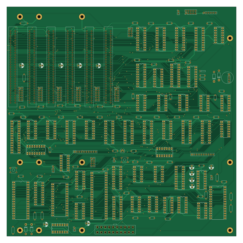
6502PC is an open source PCB design by danwerner21, published on GitHub. It is a 2-layer board measuring 244 × 244 mm, with 154 components from 62 distinct parts.
Other key parts include the 74LS04, 74LS244, 74LS682, 74LS86 and 74LS02. By type, the board carries 64 capacitors, 46 ICs, 23 connectors, 9 resistors, 4 diodes and 2 jumpers.
It belongs with the retro computing designs in this gallery.
From the project
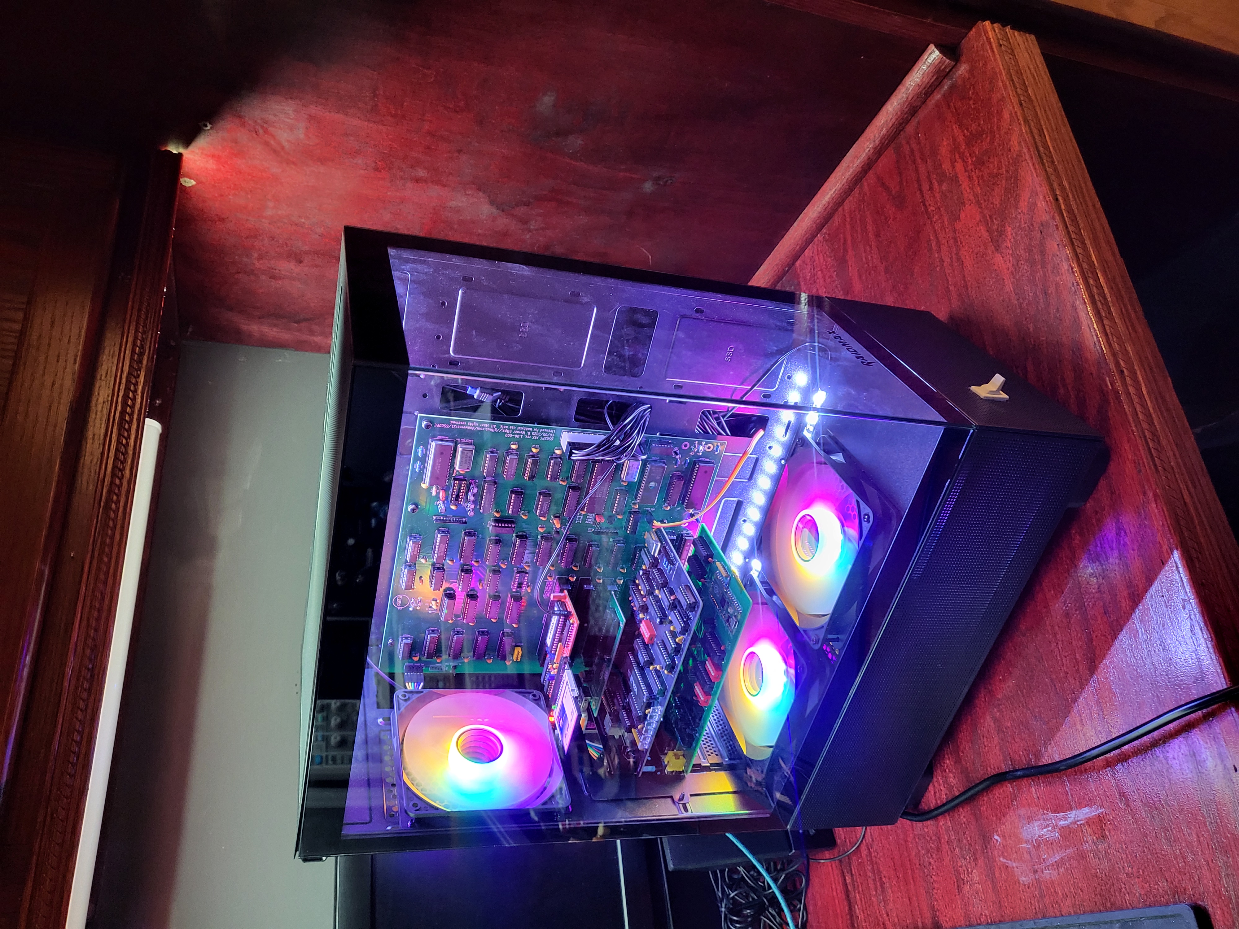
6502 ATX motherboard
See this repo (https://github.com/danwerner21/6x0x-DOS65) for ROM image and operating system.
Patches: Lift Pin 1 of u5 74ls02. Tie the socket of U5 pin 1 to ground. U47 SCRATCH CONNECTION TO PIN 3 ON BOTTOM OF PCB. TIE U47 PIN 3 TO +5V (DO NOT USE PIN 18 OF U47)
Contrary to what is on the Schematic, the battery connector will not support a supercap, a battery is required.
Main components on the 6502PC
6502PC bill of materials (BOM)
154 components, 62 distinct parts.
| Qty | Part | Footprint | Refs |
|---|---|---|---|
| 1 | 74LS04 | STD_DDW_DIP14 | U1 |
| 6 | 74LS244 | STD_DDW_DIP20 | U2, U34, U36, U39, U45, U46 |
| 1 | 74LS682 | STD_DDW_DIP20 | U3 |
| 1 | 74LS86 | STD_DDW_DIP14 | U4 |
| 1 | 74LS02 | STD_DDW_DIP14 | U5 |
| 2 | 74LS00 | STD_DDW_DIP14 | U6, U21 |
| 3 | 74LS32 | STD_DDW_DIP14 | U7, U10, U16 |
| 1 | SRAM_512K | STD_DDW_DIP32 | U8 |
| 2 | 74LS08 | STD_DDW_DIP14 | U9, U15 |
| 1 | 27C256 | STD_DDW_DIP28 | U11 |
| 2 | 74LS74 | STD_DDW_DIP14 | U12, U22 |
| 1 | 6502 | STD_DDW_DIP40 | U13 |
| 1 | 74LS14 | STD_DDW_DIP14 | U17 |
| 1 | 74LS06 | STD_DDW_DIP14 | U18 |
| 1 | 74HCT14 | STD_DDW_DIP14 | U19 |
| 1 | 74LS688 | STD_DDW_DIP20 | U23 |
| 2 | 74LS138 | STD_DDW_DIP16 | U24, U42 |
| 6 | 74LS245 | STD_DDW_DIP20 | U25, U26, U27, U28, U32, U41 |
| 1 | DS1233 | STD_DDW_TO92 | U29 |
| 1 | 74LS163 | STD_DDW_DIP16 | U30 |
Show 42 more
| Qty | Part | Footprint | Refs |
|---|---|---|---|
| 1 | 74LS240 | STD_DDW_DIP20 | U31 |
| 1 | 74LS174 | STD_DDW_DIP16 | U35 |
| 1 | 74LS157 | STD_DDW_DIP16 | U37 |
| 1 | 74LS374 | STD_DDW_DIP20 | U38 |
| 1 | SRAM-32K | STD_DDW_DIP28_SKINNY | U40 |
| 2 | 74LS257 | STD_DDW_DIP16 | U43, U44 |
| 1 | M6242 | STD_DDW_DIP18 | U47 |
| 1 | G65SC51P | STD_DDW_DIP28 | U48 |
| 1 | MAX232 | STD_DDW_DIP16 | U49 |
| 1 | RTC_OSC | DDW_STD_RTCCRYSTAL | X1 |
| 6 | IRQ Selection | STD_DDW_PINHEAD_V_2x06 | J1, J2, J5, J7, J9, J13 |
| 6 | Bus_ISA_8bit | BUSPC_HOST | J3, J4, J6, J8, J10, J14 |
| 1 | TTL SERIAL CONSOLE | STD_DDW_PINHEAD_V_1x06 | J11 |
| 1 | TTL CONSOLE PWR | STD_DDW_PINHEAD_V_1x02 | J12 |
| 1 | SHADOW ADDR | STD_DDW_PINHEAD_V_2x04 | P1 |
| 1 | CONN_10X2 | ATXConnector | P11 |
| 1 | POWER_SW | STD_DDW_PINHEAD_V_1x02 | P12 |
| 1 | 14.31818 MHz CLK | STD_DDW_DIP14 | P13 |
| 1 | 16.000Mhz | STD_DDW_DIP14 | P14 |
| 1 | CPU CLOCK SPEED | STD_DDW_PINHEAD_V_2x04 | P15 |
| 1 | CONN_4 | STD_DDW_PINHEAD_V_1x04 | P16 |
| 1 | 1.8432 MHz CLK | STD_DDW_DIP14 | P17 |
| 1 | SERIAL | STD_DDW_PINHEAD_V_2x05 | P18 |
| 2 | JUMPER | STD_DDW_PINHEAD_V_1x02 | JP1, JP3 |
| 1 | ROM SELECT | STD_DDW_PINHEAD_V_1x03 | K1 |
| 1 | 2200 | STD_DDW_SIP10 | RR1 |
| 1 | 22K | STD_DDW_SIP10 | RR2 |
| 1 | POWER | STD_DDW_TACTSW | SW1 |
| 1 | RESET | STD_DDW_TACTSW | SW2 |
| 2 | 1N4148 | STD_DDW_DIODE | D1, D2 |
| 2 | D | STD_DDW_DIODE | D3, D4 |
| 5 | 22 uF | STD_DDW_PCAP | C1, C2, C3, C4, C17 |
| 49 | 0.1 uF | STD_DDW_CAP | C5, C6, C7, C8, C9, C10, C11, C12 +41 |
| 1 | 1uF | STD_DDW_PCAP | C28 |
| 1 | 10uF | STD_DDW_PCAP | C35 |
| 1 | 0.01 uF | STD_DDW_CAP | C57 |
| 2 | 15pf | STD_DDW_CAP | C59, C60 |
| 5 | 1.0 uF | STD_DDW_PCAP | C61, C63, C64, C65, C66 |
| 2 | 10k | STD_DDW_RESISTOR | R1, R3 |
| 1 | 470 | STD_DDW_RESISTOR | R2 |
| 3 | 4.7K | STD_DDW_RESISTOR | R4, R7, R26 |
| 3 | 1000 | STD_DDW_RESISTOR | R5, R6, R8 |
6502PC design files
The KiCad project lives in the danwerner21/6502PC repository on GitHub; these links point at the commit this page was built from.
- Layout6502PC-6U.kicad_pcb
- Schematic6502PC-6U.kicad_sch
6502PC: common questions
How big is the 6502PC PCB?
The 6502PC measures 244 × 244 mm, has 2 copper layers and is 1.6 mm thick.
How many components are on the 6502PC?
154 components, from 62 distinct parts. The full bill of materials is listed on this page.
Where can I download the 6502PC design files?
From the danwerner21/6502PC repository on GitHub, which has the KiCad layout and the schematic; the links under Design files point to each one.
Can I use the 6502PC design in my own project?
The repository has no license, so all rights stay with danwerner21. Use it as a reference, and ask the author before reusing the design.
Similar boards
Amiga External
hoglet67
21.9 × 76.7 mm6 parts2LGPL-3.01.0k
Atari pickup
26.4 × 53.9 mm7 parts2LGPL-3.01.0k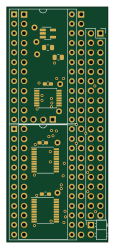
Deniseadapter
26.7 × 62.2 mm16 parts2LGPL-3.01.0k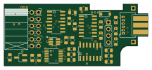
Analog
53.9 × 23.2 mm33 parts2LGPL-3.01.0k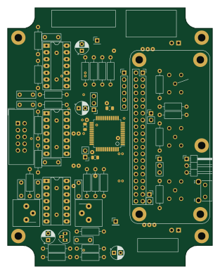
Rgb to hdmi
77 × 97 mm67 parts2LGPL-3.01.0k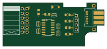
Buffer
53.9 × 23.2 mm13 parts2LGPL-3.01.0k