
10 open source boards using the ADS1299
Real designs built with the ADS1299, from public GitHub projects: a quick way to see how others power, decouple and connect it. Each board comes with its KiCad files, full parts list and a render — and you can simulate its firmware on HardLabs.
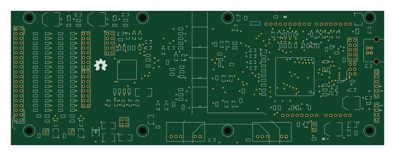 AVR/Arduino
Arduino ads129x
OpenElectronicsLab
197 × 71 mm267 partsGPL-3.0102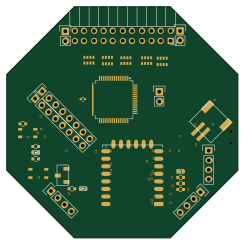 ESP8266
OpenBCI Wifi Shield
OpenBCI
61.2 × 61.2 mm67 parts2LCustom license22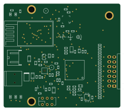
Brainboard wearable v2
gskelly
61.1 × 54.6 mm134 partsNo license21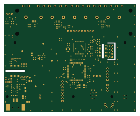 NXP
BioAmp v1.1.0
prototipado
120 × 98 mm111 parts2LBSD-3-Clause16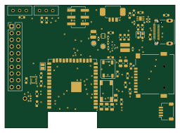 ESP32
FreeEEG
eric5512
64 × 46.1 mm94 parts4LMIT5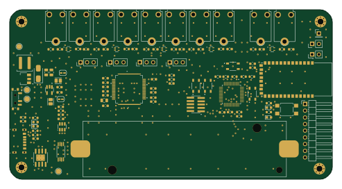 NXP
Eeg headset project
lolobernardi
123 × 64.5 mm108 parts2LCustom license0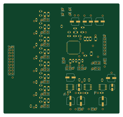
EEG
IIBM
100.5 × 95.8 mm107 parts2LNo license0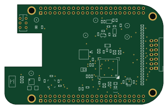
Brainboardv2
86.4 × 54.6 mm105 partsNo license21 STM32
Bioelectronics
embeddedos-org
160 × 120 mm641 parts12LMIT8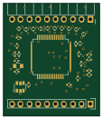
ThinkerAFE
biomurph
28.1 × 32.6 mm57 parts4LNo license0
How designs wire the ADS1299
Read from the KiCad layouts of 8 open source designs, one per repository: what each pin of the ADS1299 connects to, and the resistors, capacitors and other passives placed on it.
- The BIASOUT_63 pin has a series resistor on 8 of 8 designs, most often 1 MΩ (then 4.99 kΩ).
- The NC_27 pin is left unconnected on 8 of 8 designs.
- The NC_29 pin is left unconnected on 8 of 8 designs.
- The RESV1_31 pin is tied to GND on 8 of 8 designs.
| Pin | Connected to | Parts on the pin |
|---|---|---|
| IN8N_1pin 1 | Connected to: A connector 25% |
|
| IN8P_2pin 2 | Connected to: A connector 25% |
|
| IN7N_3pin 3 | Connected to: A connector 25% |
|
| IN7P_4pin 4 | Connected to: A connector 25% |
|
| IN6N_5pin 5 | Connected to: A connector 25% |
|
| IN6P_6pin 6 | Connected to: A connector 25% |
|
| IN5N_7pin 7 | Connected to: A connector 25% |
|
| IN5P_8pin 8 | Connected to: A connector 25% |
|
| IN4N_9pin 9 | Connected to: A connector 25% |
|
| IN4P_10pin 10 | Connected to: A connector 25% |
|
| IN3N_11pin 11 | Connected to: A connector 25% |
|
| IN3P_12pin 12 | Connected to: A connector 25% |
|
| IN2N_13pin 13 | Connected to: A connector 25% |
|
| IN2P_14pin 14 | Connected to: A connector 25% |
|
| IN1N_15pin 15 | Connected to: A connector 25% |
|
| IN1P_16pin 16 | Connected to: A connector 25% |
|
| AVDD_19pin 19 | Connected to: 5V 88% |
|
| AVSS_20pin 20 | Connected to: GND 75% · -2.5V 25% | — |
| AVDD_21pin 21 | Connected to: 5V 88% |
|
| AVDD_22pin 22 | Connected to: 5V 88% |
|
| AVSS_23pin 23 | Connected to: GND 75% · -2.5V 25% | — |
| VREFP_24pin 24 | Connected to: Signal 88% |
|
| VREFN_25pin 25 | Connected to: GND 75% · -2.5V 25% | — |
| VCAP4_26pin 26 | Connected to: Signal 100% |
|
| NC_27pin 27 | Connected to: Not connected 100% | — |
| VCAP1_28pin 28 | Connected to: Signal 100% |
|
| NC_29pin 29 | Connected to: Not connected 100% | — |
| VCAP2_30pin 30 | Connected to: Signal 100% |
|
| RESV1_31pin 31 | Connected to: GND 100% | — |
| AVSS_32pin 32 | Connected to: GND 75% · -2.5V 25% | — |
| DGND_33pin 33 | Connected to: GND 100% | — |
| PWDN_35pin 35 | Connected to: The microcontroller 25% · VDD 25% |
|
| DAISY_IN_41pin 41 | Connected to: GND 88% | — |
| GPIO1_42pin 42 | Connected to: Signal 63% · not connected 38% |
|
| GPIO2_44pin 44 | Connected to: Signal 63% · not connected 38% |
|
| GPIO3_45pin 45 | Connected to: Signal 63% · not connected 38% |
|
| GPIO4_46pin 46 | Connected to: Signal 63% · not connected 38% |
|
| DVDD_48pin 48 | Connected to: 3.3V 88% |
|
| DGND_49pin 49 | Connected to: GND 100% | — |
| DVDD_50pin 50 | Connected to: 3.3V 88% |
|
24 more pins vary from design to design. Connections count pins, parts count designs; values in brackets are how many parts had that value. Designs read include Arduino ads129x by OpenElectronicsLab, OpenBCI Wifi Shield by OpenBCI, Brainboard wearable v2 by gskelly and BioAmp v1.1.0 by prototipado.
The ADS1299 in open source designs
The gallery holds 10 open source boards using the ADS1299 from 9 GitHub repositories; a typical one measures about 93.4 × 62.9 mm and carries around 108 components.
57% are two-layer designs, the rest use four layers or more, and 40% carry an open source license.
The most starred is Arduino ads129x by OpenElectronicsLab.
Parts used alongside the ADS1299
Microcontrollers on boards using the ADS1299
What boards using the ADS1299 are built for
ADS1299: common questions
Where can I find a ADS1299 reference design?
Each of the 10 boards on this page is a real design using the ADS1299. Open one to see how it is wired up, with the full BOM, a render of the layout and links to its KiCad files.
What resistor goes on the ADS1299 BIASOUT_63 pin?
The BIASOUT_63 pin has a series resistor on 8 of 8 designs, most often 1 MΩ (then 4.99 kΩ). Counted from the KiCad layouts of 8 open source designs using the ADS1299.
How is the ADS1299 NC_27 pin connected?
The NC_27 pin is left unconnected on 8 of 8 designs. Counted from the KiCad layouts of 8 open source designs using the ADS1299.
How is the ADS1299 NC_29 pin connected?
The NC_29 pin is left unconnected on 8 of 8 designs. Counted from the KiCad layouts of 8 open source designs using the ADS1299.
What parts are used alongside the ADS1299?
The TPD4E1B06, AP2112K-3.3TRG1, TPD2E001DRLR and TPS72325 appear in the most repositories here.
Which microcontrollers do boards using the ADS1299 use?
Most are built on NXP (2), AVR/Arduino (1), ESP32 (1) and ESP8266 (1).
How big is a typical board using the ADS1299?
The median is 93.4 × 62.9 mm, and 57% are two-layer designs.
What is the most popular open source board using the ADS1299?
By GitHub stars, Arduino ads129x by OpenElectronicsLab, with 102 stars.
Can I simulate one of these boards using the ADS1299 before building it?
Yes. HardLabs turns a board's netlist and BOM into a working simulation, so you can boot and test firmware against it with no hardware on your desk.