
7 open source boards using the PCM2704CDBR
Real designs built with the PCM2704CDBR, from public GitHub projects: a quick way to see how others power, decouple and connect it. Each board comes with its KiCad files, full parts list and a render — and you can simulate its firmware on HardLabs.
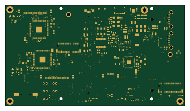 Raspberry Pi
The 4DS
Astronuat21
160 × 90 mm347 parts4LAGPL-3.05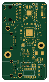
Skibidi thinkbook-14-hub
tobycm
40 × 70 mm94 parts4LMIT1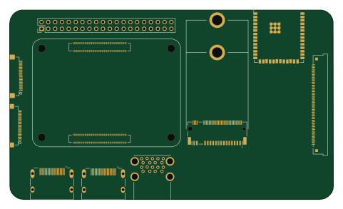 ESP32
Felső panel
NBence0
120.1 × 70.2 mm274 parts6LNo license0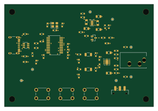
Pr2-usb headphone amplifier
seanahuynh
80 × 55 mm62 parts4LNo license0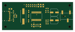
PCM270-DAC
411568
65 × 26 mm31 parts2LMIT0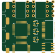
AK4490DAC
fTomo-robot
28.1 × 27.1 mm14 parts2LNo license0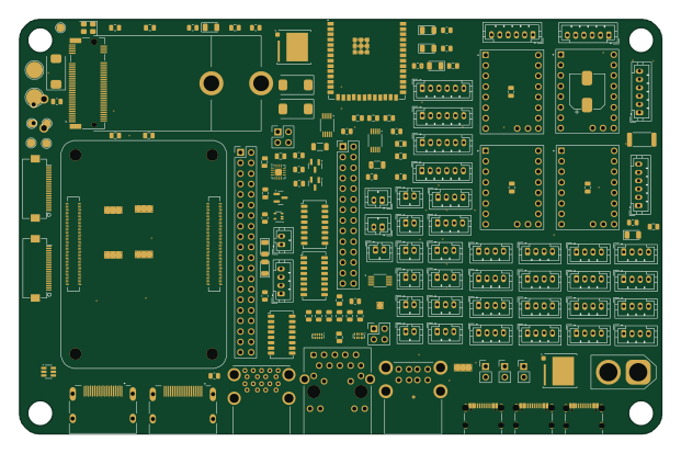 Raspberry Pi
CM5IO második terv
155 × 100 mm174 parts6LNo license0
How designs wire the PCM2704CDBR
Read from the KiCad layouts of 5 open source designs, one per repository: what each pin of the PCM2704CDBR connects to, and the resistors, capacitors and other passives placed on it.
- The XTO pin has a crystal on 5 of 5 designs, most often 12 MHz (then 5 MHz).
- The VCOM pin has a capacitor to GND on 5 of 5 designs, most often 10 µF (then 1 µF).
- The XTI pin has a crystal on 5 of 5 designs, most often 12 MHz (then 5 MHz).
- The CK pin is left unconnected on 5 of 5 designs.
| Pin | Connected to | Parts on the pin |
|---|---|---|
| XTOpin 1 | Connected to: Signal 100% |
|
| CKpin 2 | Connected to: Not connected 100% | — |
| DTpin 3 | Connected to: Signal 60% · not connected 40% |
|
| PSELpin 4 | Connected to: VBUS 40% · GND 20% · a signal 40% |
|
| DOUTpin 5 | Connected to: Not connected 100% | — |
| DGNDpin 6 | Connected to: GND 100% | — |
| VDDpin 7 | Connected to: 3.3V 80% · a signal 20% |
|
| D-pin 8 | Connected to: Signal 100% |
|
| D+pin 9 | Connected to: Signal 100% |
|
| VBUSpin 10 | Connected to: 3.3V 100% | — |
| ZGNDpin 11 | Connected to: GND 100% | — |
| AGNDLpin 12 | Connected to: GND 100% | — |
| VCCLpin 13 | Connected to: Signal 80% · 3.3V 20% |
|
| VOUTLpin 14 | Connected to: Signal 100% |
|
| VOUTRpin 15 | Connected to: Signal 100% |
|
| VCCRpin 16 | Connected to: Signal 80% · 3.3V 20% |
|
| AGNDRpin 17 | Connected to: GND 100% | — |
| VCOMpin 18 | Connected to: Signal 100% |
|
| PGNDpin 19 | Connected to: GND 100% | — |
| VCCPpin 20 | Connected to: Signal 80% · 3.3V 20% |
|
| HOSTpin 21 | Connected to: VBUS 80% · GND 20% | — |
| TEST1pin 25 | Connected to: Signal 60% · 3.3V 40% |
|
| TEST0pin 26 | Connected to: Signal 60% · 3.3V 40% |
|
| SSPNDpin 27 | Connected to: Signal 80% · 3.3V 20% |
|
| XTIpin 28 | Connected to: Signal 100% |
|
3 more pins vary from design to design. Connections count pins, parts count designs; values in brackets are how many parts had that value. Designs read include The 4DS by Astronuat21, Skibidi thinkbook-14-hub by tobycm, PCM270-DAC by 411568 and CM5IO második terv by NBence0.
The PCM2704CDBR in open source designs
The gallery holds 7 open source boards using the PCM2704CDBR from 6 GitHub repositories; a typical one measures about 80 × 70 mm and carries around 94 components.
71% use four copper layers or more, and 43% carry an open source license.
The most starred is The 4DS by Astronuat21.
Parts used alongside the PCM2704CDBR
Microcontrollers on boards using the PCM2704CDBR
What boards using the PCM2704CDBR are built for
PCM2704CDBR: common questions
Where can I find a PCM2704CDBR reference design?
Each of the 7 boards on this page is a real design using the PCM2704CDBR. Open one to see how it is wired up, with the full BOM, a render of the layout and links to its KiCad files.
How is the PCM2704CDBR XTO pin connected?
The XTO pin has a crystal on 5 of 5 designs, most often 12 MHz (then 5 MHz). Counted from the KiCad layouts of 5 open source designs using the PCM2704CDBR.
How is the PCM2704CDBR VCOM pin connected?
The VCOM pin has a capacitor to GND on 5 of 5 designs, most often 10 µF (then 1 µF). Counted from the KiCad layouts of 5 open source designs using the PCM2704CDBR.
How is the PCM2704CDBR XTI pin connected?
The XTI pin has a crystal on 5 of 5 designs, most often 12 MHz (then 5 MHz). Counted from the KiCad layouts of 5 open source designs using the PCM2704CDBR.
Which microcontrollers do boards using the PCM2704CDBR use?
Most are built on Raspberry Pi (2) and ESP32 (1).
How big is a typical board using the PCM2704CDBR?
The median is 80 × 70 mm, and 29% are two-layer designs.
What is the most popular open source board using the PCM2704CDBR?
By GitHub stars, The 4DS by Astronuat21, with 5 stars.
Can I simulate one of these boards using the PCM2704CDBR before building it?
Yes. HardLabs turns a board's netlist and BOM into a working simulation, so you can boot and test firmware against it with no hardware on your desk.