
5 open source boards using the MAX3232CDR
Real designs built with the MAX3232CDR, from public GitHub projects: a quick way to see how others power, decouple and connect it. Each board comes with its KiCad files, full parts list and a render — and you can simulate its firmware on HardLabs.
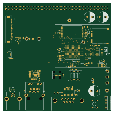 STM32
Stm32mp135 test board
js216
100 × 100 mm193 parts6LNo license4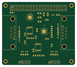
Alex-Harris-Capstone
achihuahua22
65.5 × 56.4 mm49 parts2LMIT1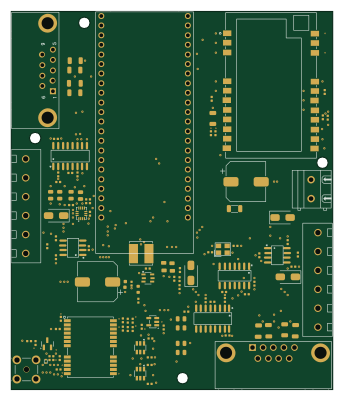 ESP32
RT Open GPS Board
rtymk
85 × 100 mm111 parts4LMIT0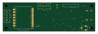 ESP32
SV-Profiler
mostapha73-rgb
85 × 27 mm53 parts4LNo license0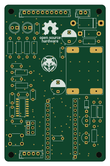
YetAnotherTNC
solmorth
55 × 85 mm36 parts2LNo license0
How designs wire the MAX3232CDR
Read from the KiCad layouts of 5 open source designs, one per repository: what each pin of the MAX3232CDR connects to, and the resistors, capacitors and other passives placed on it.
- The C1+_1 pin has a series capacitor on 4 of 5 designs, most often 100 nF.
- The V+_2 pin has a capacitor to GND on 4 of 5 designs, most often 100 nF.
- The C1-_3 pin has a series capacitor on 4 of 5 designs, most often 100 nF.
- The C2+_4 pin has a series capacitor on 4 of 5 designs, most often 100 nF.
| Pin | Connected to | Parts on the pin |
|---|---|---|
| C1+_1pin 1 | Connected to: Signal 100% |
|
| V+_2pin 2 | Connected to: Signal 100% |
|
| C1-_3pin 3 | Connected to: Signal 80% · not connected 20% |
|
| C2+_4pin 4 | Connected to: Signal 80% · not connected 20% |
|
| C2-_5pin 5 | Connected to: Signal 80% · 3.3V 20% |
|
| V-_6pin 6 | Connected to: Signal 100% |
|
| GND_15pin 15 | Connected to: GND 80% · not connected 20% | — |
| VCC_16pin 16 | Connected to: 3.3V 60% · not connected 20% · a signal 20% |
|
8 more pins vary from design to design. Connections count pins, parts count designs; values in brackets are how many parts had that value. Designs read include Stm32mp135 test board by js216, Alex-Harris-Capstone by achihuahua22, SV-Profiler by mostapha73-rgb and RT Open GPS Board by rtymk.
The MAX3232CDR in open source designs
The gallery holds 5 open source boards using the MAX3232CDR from 5 GitHub repositories; a typical one measures about 85 × 85 mm and carries around 53 components.
60% use four copper layers or more, and 40% carry an open source license.
The most starred is Stm32mp135 test board by js216.
What boards using the MAX3232CDR are built for
MAX3232CDR: common questions
Where can I find a MAX3232CDR reference design?
Each of the 5 boards on this page is a real design using the MAX3232CDR. Open one to see how it is wired up, with the full BOM, a render of the layout and links to its KiCad files.
How is the MAX3232CDR C1+_1 pin connected?
The C1+_1 pin has a series capacitor on 4 of 5 designs, most often 100 nF. Counted from the KiCad layouts of 5 open source designs using the MAX3232CDR.
How is the MAX3232CDR V+_2 pin connected?
The V+_2 pin has a capacitor to GND on 4 of 5 designs, most often 100 nF. Counted from the KiCad layouts of 5 open source designs using the MAX3232CDR.
How is the MAX3232CDR C1-_3 pin connected?
The C1-_3 pin has a series capacitor on 4 of 5 designs, most often 100 nF. Counted from the KiCad layouts of 5 open source designs using the MAX3232CDR.
Which microcontrollers do boards using the MAX3232CDR use?
Most are built on ESP32 (2) and STM32 (1).
How big is a typical board using the MAX3232CDR?
The median is 85 × 85 mm, and 40% are two-layer designs.
What is the most popular open source board using the MAX3232CDR?
By GitHub stars, Stm32mp135 test board by js216, with 4 stars.
Can I simulate one of these boards using the MAX3232CDR before building it?
Yes. HardLabs turns a board's netlist and BOM into a working simulation, so you can boot and test firmware against it with no hardware on your desk.