
15 open source boards using the TLC555CDR
Real designs built with the TLC555CDR, from public GitHub projects: a quick way to see how others power, decouple and connect it. Each board comes with its KiCad files, full parts list and a render — and you can simulate its firmware on HardLabs.
 NXP
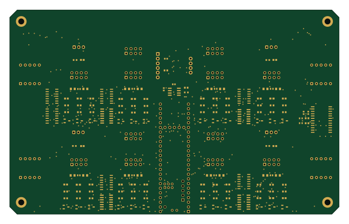
LegRobotBoardTeensy
01binary
178.2 × 111 mm154 parts2LNo license20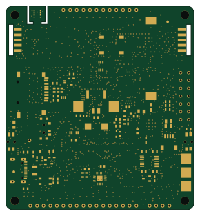 ESP32
Soldered Inkplate 4 TEMPERA with glass panel
SolderedElectronics
72 × 78 mm246 parts4LTAPR-OHL-1.05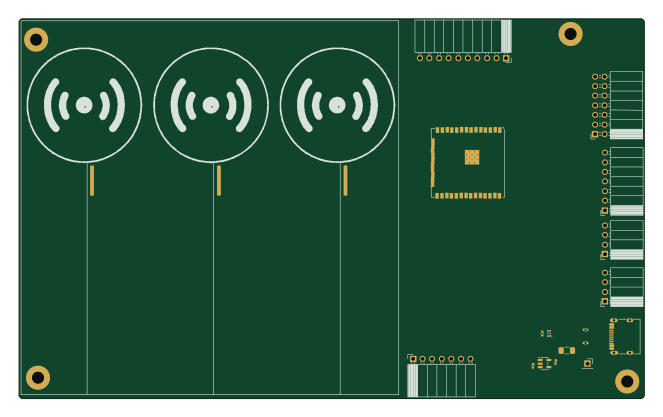 ESP32
Intelligent-Traffic-Simulator
LimesKey
165.5 × 100.5 mm148 parts4LApache-2.01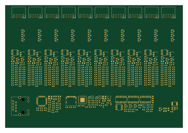 ESP32
Compact-S1-placement
ddasdkimo
160 × 110 mm694 parts2LNo license0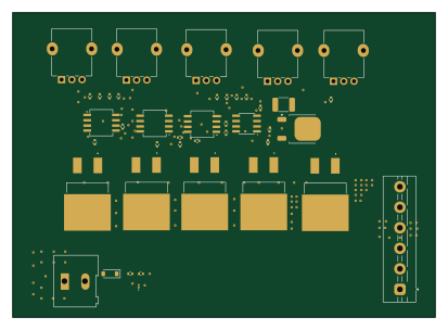
Led dimmer pot controller
manhoosbilli1
103 × 74.2 mm42 parts2LNo license0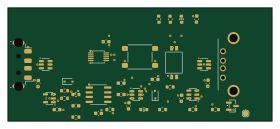
Usb replug
clankagent
70 × 30 mm39 parts4LNo license0
ECE Openhouse Souvenir
patthananb
30 × 30 mm25 parts2LNo license0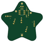
PCBs
ajkumar-1907
42.3 × 40.7 mm18 parts2LNo license0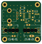
LED Dimmer
RossPorter506
34.5 × 35.8 mm18 parts2LNo license0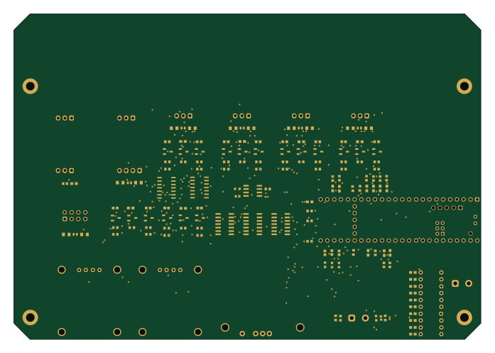 NXP
MainRobotBoardTeensy
174.1 × 121.1 mm145 parts2LNo license20 ESP32
Soldered Inkplate 4 TEMPERA with glass panel panel
1.9 × 12 mm246 parts4LTAPR-OHL-1.05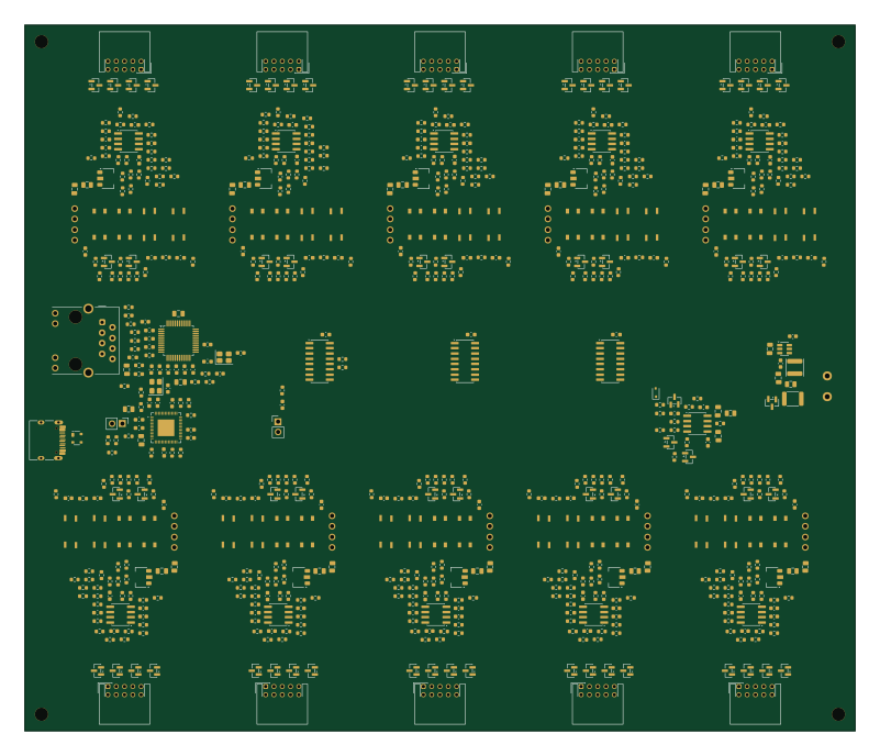 ESP32
Layout-S2-review
200 × 170 mm694 parts2LNo license0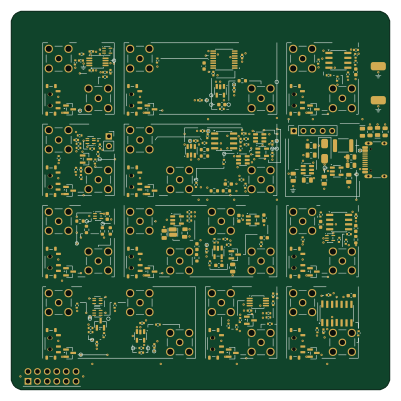
Amod c
gallicchio
100 × 100 mm211 parts4LCERN-OHL-P-2.00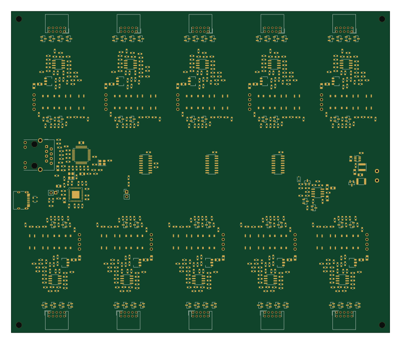 ESP32
Routing-R0
200 × 170 mm694 parts2LNo license0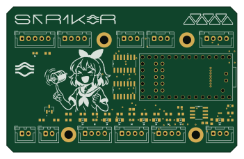
ArmRobotBoardTeensy
87.5 × 55 mm37 parts2LNo license20
How designs wire the TLC555CDR
Read from the KiCad layouts of 10 open source designs, one per repository: what each pin of the TLC555CDR connects to, and the resistors, capacitors and other passives placed on it.
- The THRES pin has a capacitor to GND on 10 of 10 designs, most often 1 µF (then 10 µF).
- The TRIG pin has a capacitor to GND on 8 of 10 designs, most often 1 µF (then 100 nF).
- The CONT pin has a capacitor to GND on 8 of 10 designs, most often 10 nF (then 100 nF).
- The DISCH pin has a series resistor on 7 of 10 designs, most often 10 kΩ (then 360 kΩ).
| Pin | Connected to | Parts on the pin |
|---|---|---|
| GNDpin 1 | Connected to: GND 100% | — |
| TRIGpin 2 | Connected to: Signal 100% |
|
| OUTpin 3 | Connected to: Signal 90% |
|
| RESETpin 4 | Connected to: VCC 70% · a signal 30% | — |
| CONTpin 5 | Connected to: Signal 90% |
|
| THRESpin 6 | Connected to: Signal 100% |
|
| DISCHpin 7 | Connected to: Signal 90% |
|
| VDDpin 8 | Connected to: VCC 80% · a signal 20% |
|
Connections count pins, parts count designs; values in brackets are how many parts had that value. Designs read include ArmRobotBoardTeensy by 01binary, Soldered Inkplate 4 TEMPERA with glass panel by SolderedElectronics, Intelligent-Traffic-Simulator by LimesKey and PCBs by ajkumar-1907.
The TLC555CDR in open source designs
The gallery holds 15 open source boards using the TLC555CDR from 10 GitHub repositories; a typical one measures about 100 × 78 mm and carries around 148 components.
67% are two-layer designs, the rest use four layers or more, and 27% carry an open source license.
The most starred is LegRobotBoardTeensy by 01binary.
What boards using the TLC555CDR are built for
TLC555CDR: common questions
Where can I find a TLC555CDR reference design?
Each of the 15 boards on this page is a real design using the TLC555CDR. Open one to see how it is wired up, with the full BOM, a render of the layout and links to its KiCad files.
How is the TLC555CDR THRES pin connected?
The THRES pin has a capacitor to GND on 10 of 10 designs, most often 1 µF (then 10 µF). Counted from the KiCad layouts of 10 open source designs using the TLC555CDR.
How is the TLC555CDR TRIG pin connected?
The TRIG pin has a capacitor to GND on 8 of 10 designs, most often 1 µF (then 100 nF). Counted from the KiCad layouts of 10 open source designs using the TLC555CDR.
How is the TLC555CDR CONT pin connected?
The CONT pin has a capacitor to GND on 8 of 10 designs, most often 10 nF (then 100 nF). Counted from the KiCad layouts of 10 open source designs using the TLC555CDR.
Which microcontrollers do boards using the TLC555CDR use?
Most are built on ESP32 (6) and NXP (2).
How big is a typical board using the TLC555CDR?
The median is 100 × 78 mm, and 67% are two-layer designs.
What is the most popular open source board using the TLC555CDR?
By GitHub stars, LegRobotBoardTeensy by 01binary, with 20 stars.
Can I simulate one of these boards using the TLC555CDR before building it?
Yes. HardLabs turns a board's netlist and BOM into a working simulation, so you can boot and test firmware against it with no hardware on your desk.