
24 open source boards using the TCA9535PWR
Real designs built with the TCA9535PWR, from public GitHub projects: a quick way to see how others power, decouple and connect it. Each board comes with its KiCad files, full parts list and a render — and you can simulate its firmware on HardLabs.
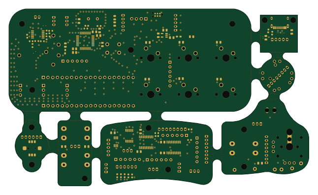 STM32
Libre-MIG
JustEnoughDucks
161.1 × 95 mm154 parts2LCERN-OHL-S-2.022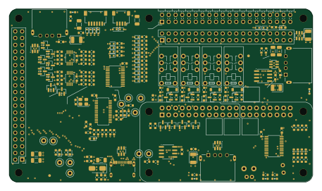 Raspberry Pi
Pinbot electronics
Pinbot-factory
114 × 65 mm204 parts4LCERN-OHL-S-2.05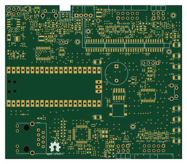 PIC
YukaLink
Misaka0x2730
94.3 × 81.8 mm235 parts4LGPL-3.03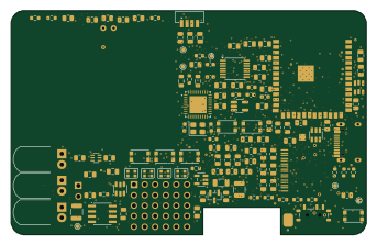 ESP32
PocketLab-Card
 Jebroa77485.6 × 54 mm250 parts4LNo license2
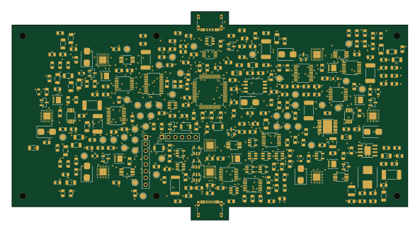 STM32
Hub
Bruhdows
148 × 78 mm309 parts4LNo license1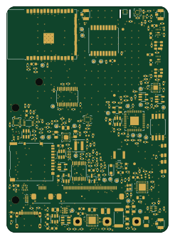 RP2040/RP2350
StratosCore
pantojinho
60 × 84 mm245 parts4LNo license1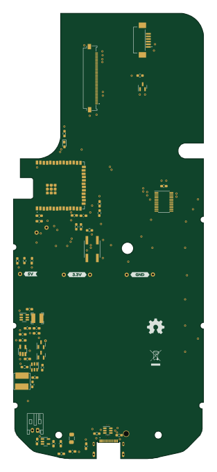 ESP32
TI83x
pjschinske
72.5 × 170 mm103 parts4LCERN-OHL-S-2.01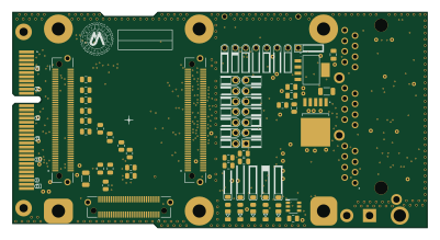
Experiment Carrier Board
andrempmattos
100 × 52 mm80 parts4LCERN-OHL-P-2.01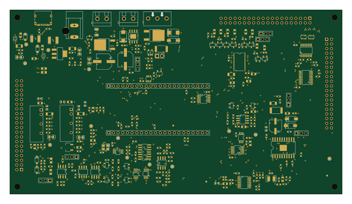
TIGP class board 2026 - main board
TIGP-Experimental-Methods
180 × 100 mm318 parts4LNo license0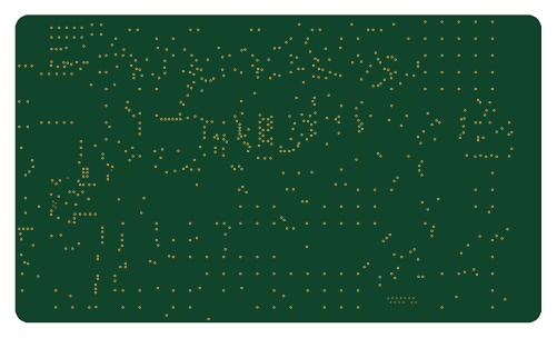 ESP32
E0005-esp32-s3-5v controller
Karpuls
125 × 73 mm268 parts4LNo license0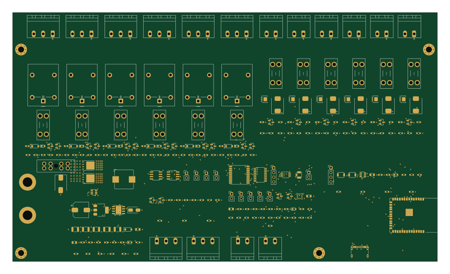 ESP32
Vancontroller
Camperlux
230 × 135 mm247 parts4LCustom license0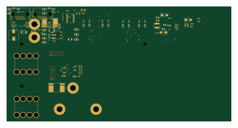
BMU v2
KomplexKapharnaum
194.9 × 100 mm125 parts4LGPL-3.00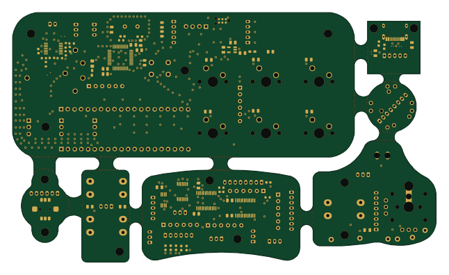 STM32
Libre-MIG-rounded
161.1 × 95 mm154 parts2LCERN-OHL-S-2.022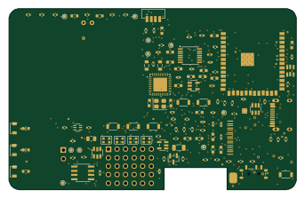 ESP32
PocketLab-Card pcba routing wip
Jebroa77485.6 × 54 mm246 parts4LNo license2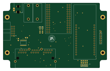
Som exp host
116 × 73 mm45 parts4LCERN-OHL-P-2.01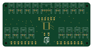
House controller multiplex breakout board v0.2.2
kevin-mitchell
97 × 48.8 mm42 parts4LNo license0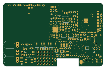 ESP32
PocketLab-Card routing working
Jebroa77485.6 × 54 mm243 parts4LNo license2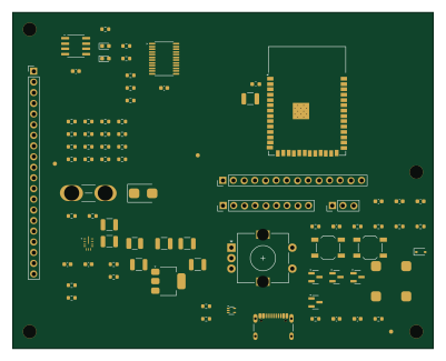 ESP32
Phase3-manager
udaravima
100 × 80 mm80 parts2LGPL-3.01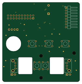
USB-C PD bench supply - UI board
GarryBGoode
70 × 72 mm51 parts2LNo license0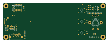
Post route
Hive-RSI-Lab
110 × 40 mm36 parts2LMIT0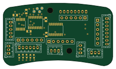
Libre-MiG IO Controller
60 × 34.3 mm31 parts2LCERN-OHL-S-2.022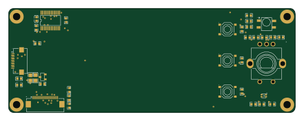
Post route auto
110 × 40 mm36 parts2LMIT0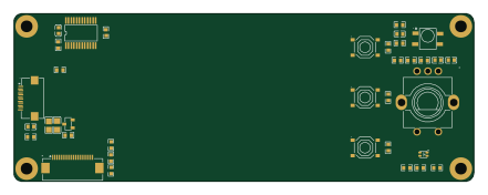
Pre route
110 × 40 mm36 parts2LMIT0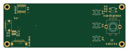
Ultra front
110 × 40 mm36 parts2LMIT0
How designs wire the TCA9535PWR
Read from the KiCad layouts of 16 open source designs, one per repository: what each pin of the TCA9535PWR connects to, and the resistors, capacitors and other passives placed on it.
- The VCC pin has a decoupling capacitor on 12 of 15 designs, most often 100 nF (then 22 µF).
- The A1 pin is tied to GND on 13 of 16 designs (a signal on 2).
- The INT pin has a pull-up to 3.3V on 10 of 16 designs, most often 10 kΩ (then 100 kΩ).
- The A2 pin is tied to GND on 12 of 16 designs (a signal on 3).
| Pin | Connected to | Parts on the pin |
|---|---|---|
| INTpin 1 | Connected to: The microcontroller 31%, a connector 25% |
|
| A1pin 2 | Connected to: GND 81% | — |
| A2pin 3 | Connected to: GND 75% · a signal 19% | — |
| P00pin 4 | Connected to: A connector 44% |
|
| P01pin 5 | Connected to: A connector 25% |
|
| P02pin 6 | Connected to: A connector 25% |
|
| P03pin 7 | Connected to: A connector 20% |
|
| P04pin 8 | Connected to: A connector 20% |
|
| P05pin 9 | Connected to: A connector 20% |
|
| P06pin 10 | Connected to: A connector 27% |
|
| P07pin 11 | Connected to: A connector 27% |
|
| GNDpin 12 | Connected to: GND 100% | — |
| P10pin 13 | Connected to: A connector 33% |
|
| P11pin 14 | Connected to: A connector 20% |
|
| P12pin 15 | Connected to: A connector 20% |
|
| P13pin 16 | Connected to: A connector 20% |
|
| P14pin 17 | Connected to: Signal 87% |
|
| P15pin 18 | Connected to: A connector 20% |
|
| A0pin 21 | Connected to: GND 67% · 3.3V 20% | — |
| SCLpin 22 | Connected to: A connector 53%, the microcontroller 33% |
|
| SDApin 23 | Connected to: A connector 53%, the microcontroller 33% |
|
| VCCpin 24 | Connected to: 3.3V 93% |
|
2 more pins vary from design to design. Connections count pins, parts count designs; values in brackets are how many parts had that value. Designs read include Libre-MIG by JustEnoughDucks, Pinbot electronics by Pinbot-factory, YukaLink by Misaka0x2730 and PocketLab-Card by Jebroa774.
The TCA9535PWR in open source designs
The gallery holds 24 open source boards using the TCA9535PWR from 16 GitHub repositories; a typical one measures about 110 × 72.5 mm and carries around 140 components.
63% use four copper layers or more, and 58% carry an open source license.
The most starred is Libre-MIG-rounded by JustEnoughDucks.
Parts used alongside the TCA9535PWR
Microcontrollers on boards using the TCA9535PWR
What boards using the TCA9535PWR are built for
TCA9535PWR: common questions
Where can I find a TCA9535PWR reference design?
Each of the 24 boards on this page is a real design using the TCA9535PWR. Open one to see how it is wired up, with the full BOM, a render of the layout and links to its KiCad files.
What decoupling capacitors do designs use on the TCA9535PWR VCC pin?
The VCC pin has a decoupling capacitor on 12 of 15 designs, most often 100 nF (then 22 µF). Counted from the KiCad layouts of 16 open source designs using the TCA9535PWR.
How is the TCA9535PWR A1 pin connected?
The A1 pin is tied to GND on 13 of 16 designs (a signal on 2). Counted from the KiCad layouts of 16 open source designs using the TCA9535PWR.
What pull-up resistor is used on the TCA9535PWR INT pin?
The INT pin has a pull-up to 3.3V on 10 of 16 designs, most often 10 kΩ (then 100 kΩ). Counted from the KiCad layouts of 16 open source designs using the TCA9535PWR.
What parts are used alongside the TCA9535PWR?
The USBLC6-2SC6, AMS1117-3.3, BQ25887RGER, ESP32-S3-WROOM-1-N8R2 and MAX-M10S-00B appear in the most repositories here.
Which microcontrollers do boards using the TCA9535PWR use?
Most are built on ESP32 (7), STM32 (3), PIC (1) and Raspberry Pi (1).
How big is a typical board using the TCA9535PWR?
The median is 110 × 72.5 mm, and 38% are two-layer designs.
What is the most popular open source board using the TCA9535PWR?
By GitHub stars, Libre-MIG-rounded by JustEnoughDucks, with 22 stars.
Can I simulate one of these boards using the TCA9535PWR before building it?
Yes. HardLabs turns a board's netlist and BOM into a working simulation, so you can boot and test firmware against it with no hardware on your desk.