
19 open source boards using the PCF8574A
Real designs built with the PCF8574A, from public GitHub projects: a quick way to see how others power, decouple and connect it. Each board comes with its KiCad files, full parts list and a render — and you can simulate its firmware on HardLabs.
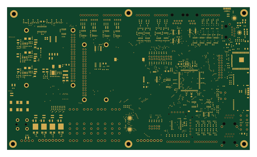 ESP32
Womo
muccc
254.9 × 150.1 mm532 parts4LGPL-3.084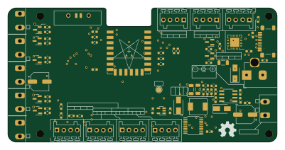 ESP8266
ESP-Hiro
Chrismettal
100 × 50 mm79 parts2LGPL-3.015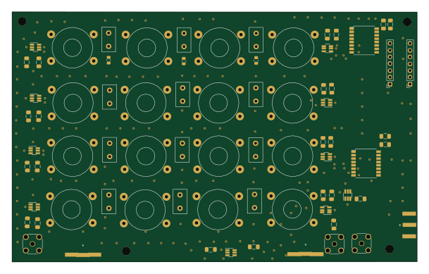
Band passfilter arduino esp32
paulh002
152 × 93.7 mm123 parts2LNo license3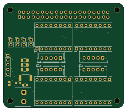
PiScope
cutec-chris
65 × 56 mm41 parts2LNo license3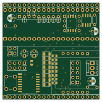
Bluepill sensor
kellerkindt
50.4 × 50.4 mm39 parts2LApache-2.03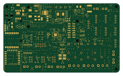 RP2040/RP2350
ANGAZA ELIMU
R-Mutura
131 × 78.5 mm207 parts4LNo license2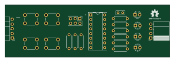
PCF8574 educational module
rsedak
89.5 × 28.3 mm22 parts2LCustom license2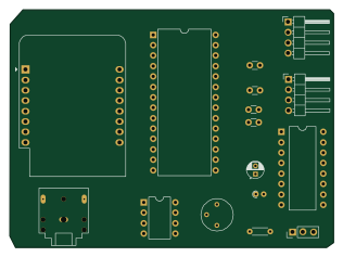 ESP8266
C64sid i2c
pappavis
78.8 × 57.9 mm16 parts2LNo license1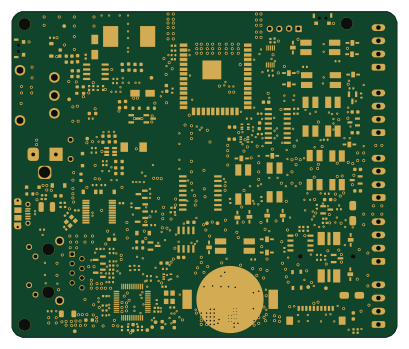 ESP32
ELISTARS
102 × 86.3 mm281 parts4LNo license0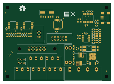 AVR/Arduino
High Torque Servo Arm: Main
akornsys-rdi
100 × 72 mm73 parts2LGPL-3.00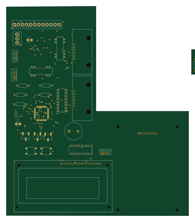 AVR/Arduino
Smart-Ventilator
yesitha
156.3 × 179.5 mm69 parts2LNo license0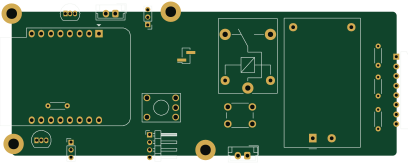 ESP8266
StroomMeterACS712
101.9 × 38.1 mm18 parts2LNo license0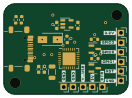
USB-CP2102-only
33 × 24 mm30 parts2LGPL-3.015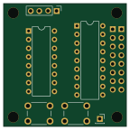
IO Expander
iNavFlight
36 × 36 mm7 parts2LNo license11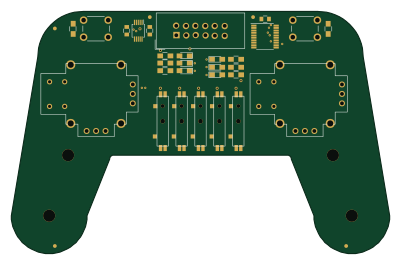
High torque servo arm remote
100 × 64 mm29 parts2LGPL-3.00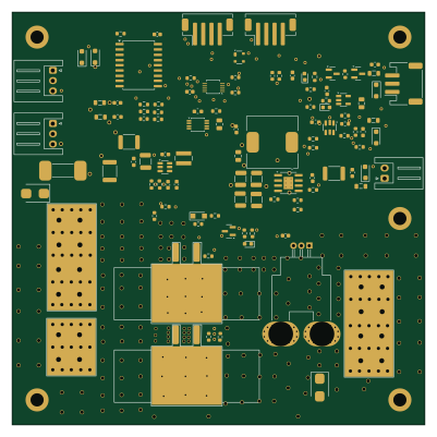
PA Power V1
M0LTE
100 × 100 mm111 parts4LNo license15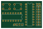
IO Expander 20x40
40.6 × 26.7 mm7 parts2LNo license11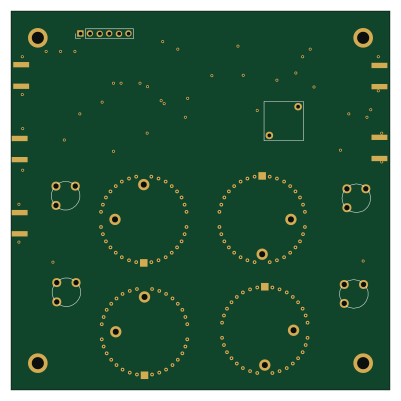
RXLNA
100 × 100 mm86 parts4LNo license15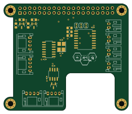 Raspberry Pi
InterfaceRaspiCAN
ARIG-Robotique
65 × 56 mm32 parts4LNo license0
How designs wire the PCF8574A
Read from the KiCad layouts of 15 open source designs, one per repository: what each pin of the PCF8574A connects to, and the resistors, capacitors and other passives placed on it.
- The INT pin is left unconnected on 11 of 15 designs (a signal on 4).
- The A1 pin has a pull-up to 3.3V on 6 of 15 designs, most often 4.7 kΩ (then 10 kΩ).
| Pin | Connected to | Parts on the pin |
|---|---|---|
| A1pin 2 | Connected to: GND 53% · a signal 47% |
|
| VSSpin 8 | Connected to: GND 73% · not connected 20% | — |
| INTpin 13 | Connected to: Not connected 73% · a signal 27% | — |
| SCLpin 14 | Connected to: A connector 73%, the microcontroller 33% |
|
| SDApin 15 | Connected to: A connector 67%, the microcontroller 33% |
|
| VDDpin 16 | Connected to: 3.3V 60% · a signal 27% |
|
10 more pins vary from design to design. Connections count pins, parts count designs; values in brackets are how many parts had that value. Designs read include Womo by muccc, ESP-Hiro by Chrismettal, PA Power V1 by M0LTE and IO Expander by iNavFlight.
The PCF8574A in open source designs
The gallery holds 19 open source boards using the PCF8574A from 15 GitHub repositories; a typical one measures about 100 × 57.9 mm and carries around 41 components.
68% are two-layer designs, the rest use four layers or more, and 32% carry an open source license.
The most starred is Womo by muccc.
Parts used alongside the PCF8574A
Microcontrollers on boards using the PCF8574A
What boards using the PCF8574A are built for
PCF8574A: common questions
Where can I find a PCF8574A reference design?
Each of the 19 boards on this page is a real design using the PCF8574A. Open one to see how it is wired up, with the full BOM, a render of the layout and links to its KiCad files.
How is the PCF8574A INT pin connected?
The INT pin is left unconnected on 11 of 15 designs (a signal on 4). Counted from the KiCad layouts of 15 open source designs using the PCF8574A.
What pull-up resistor is used on the PCF8574A A1 pin?
The A1 pin has a pull-up to 3.3V on 6 of 15 designs, most often 4.7 kΩ (then 10 kΩ). Counted from the KiCad layouts of 15 open source designs using the PCF8574A.
What parts are used alongside the PCF8574A?
The CP2102N-A01-GQFN28, TBU-CA065-200-WH and WeMos_D1_mini appear in the most repositories here.
Which microcontrollers do boards using the PCF8574A use?
Most are built on ESP8266 (3), AVR/Arduino (2), ESP32 (2) and Raspberry Pi (1).
How big is a typical board using the PCF8574A?
The median is 100 × 57.9 mm, and 68% are two-layer designs.
What is the most popular open source board using the PCF8574A?
By GitHub stars, Womo by muccc, with 84 stars.
Can I simulate one of these boards using the PCF8574A before building it?
Yes. HardLabs turns a board's netlist and BOM into a working simulation, so you can boot and test firmware against it with no hardware on your desk.