
24 open source boards using the BQ25798RQMR
Real designs built with the BQ25798RQMR, from public GitHub projects: a quick way to see how others power, decouple and connect it. Each board comes with its KiCad files, full parts list and a render — and you can simulate its firmware on HardLabs.
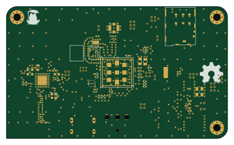 Nordic nRF
Ribbit network frog hardware
Ribbit-Network
84 × 50 mm160 parts6LMIT106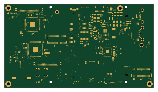 Raspberry Pi
The 4DS
Astronuat21
160 × 90 mm347 parts4LAGPL-3.05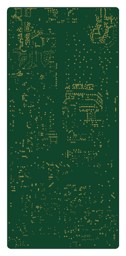 ESP32
Parsnip
LimesKey
60 × 130 mm400 parts4LCC-BY-NC-4.04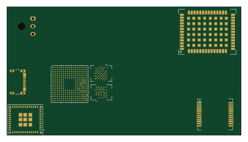 ESP32
Open race v2
teehee567
90.5 × 49.5 mm329 parts8LNo license4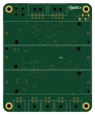 STM32
Power board
tudsat-rocket
78 × 95 mm142 parts4LNo license3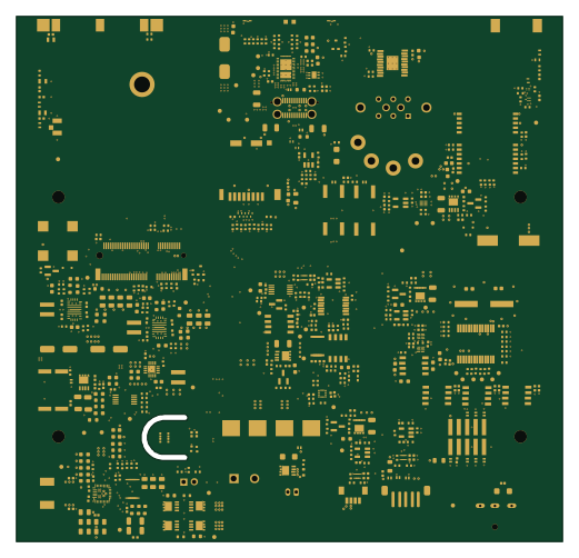
Flatburn lte
MIT-Senseable-City-Lab
130 × 125 mm542 parts4LMIT1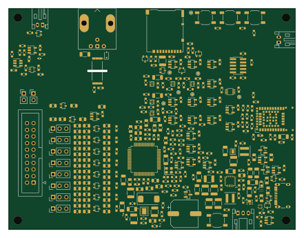
EEG
MariusFauteux
110 × 85 mm370 parts4LNo license1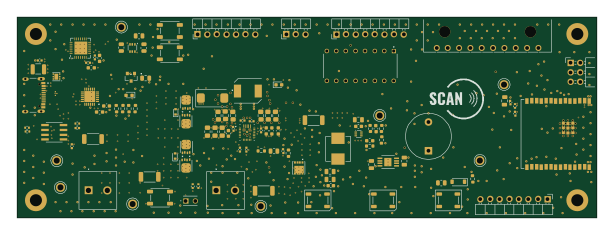 ESP32
SCAN
jjsprandel
153.3 × 53 mm181 parts6LCC-BY-NC-4.01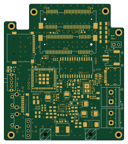 ESP32
BeeFASYER SPARROW
beewarden
64.1 × 72.8 mm121 parts4LCERN-OHL-S-2.01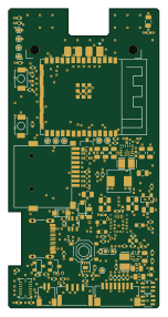 ESP32
Tresvizo main
cadaritre
36 × 71.5 mm106 parts4LNo license1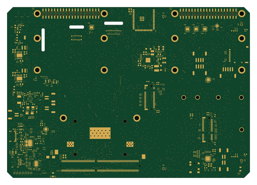 ESP32
Fibel2
nikolozka
210 × 148 mm434 parts4LNo license0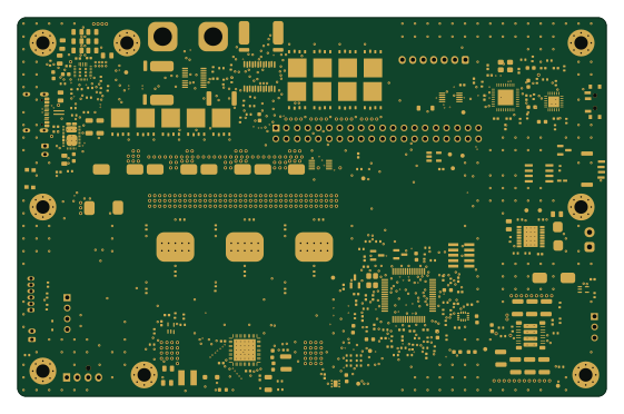 STM32
Atlas drive
AtlasAutoware
140 × 90 mm377 parts6LNo license0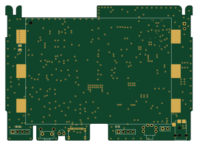 ESP32
Pcb openair max main
Open-Air-Foundation
99.5 × 72 mm235 parts4LCC-BY-SA-4.00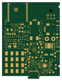 ESP32
Main routed
0x63616c
54 × 71 mm194 parts4LNo license0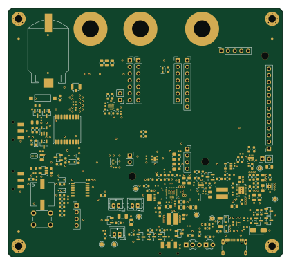
Airgrep
mp911de
105 × 95 mm175 parts4LNo license0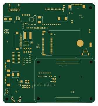
Minerva-Carrier
PyroFlareX
83.5 × 90 mm173 parts6LNo license0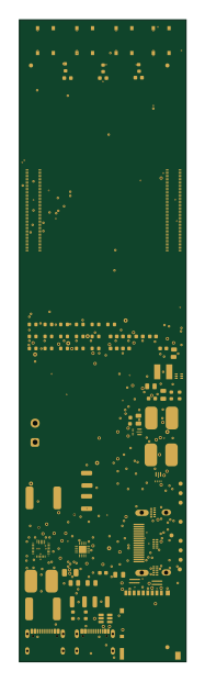
Tablet-Project
ShresthRao
40.3 × 155 mm115 parts4LNo license0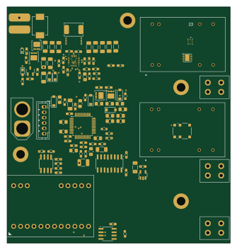 STM32
Bottom
StanZalewski
83.3 × 88.1 mm115 parts4LNo license0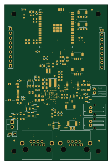 ESP32
SunSproutHub
JohnNeville
56 × 85 mm98 parts6LCERN-OHL-S-2.00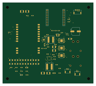 Nordic nRF
RoyalNode
jb66dmg52h-dotcom
97 × 87 mm71 parts4LNo license0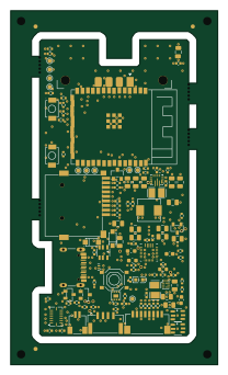 ESP32
Tresvizo panel
50 × 85.5 mm106 parts4LNo license1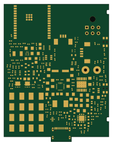 ESP32
Main test
54 × 71 mm194 parts4LNo license0
Goosepack
Marsgate
50 × 23 mm69 parts4LNo license0
Goosepack2s
45 × 23 mm64 parts4LNo license0
How designs wire the BQ25798RQMR
Read from the KiCad layouts of 21 open source designs, one per repository: what each pin of the BQ25798RQMR connects to, and the resistors, capacitors and other passives placed on it.
- The BTST1_4 pin has a series capacitor on 21 of 21 designs, most often 47 nF.
- The BTST2_19 pin has a series capacitor on 21 of 21 designs, most often 47 nF.
- The SW2_26 pin has a series capacitor on 21 of 21 designs, most often 47 nF.
- The SW2_26 pin has a inductor on 21 of 21 designs, most often 1 µH (then 2.2 µH).
| Pin | Connected to | Parts on the pin |
|---|---|---|
| VBUS_2pin 2 | Connected to: Signal 52% · VBUS 48% |
|
| VBUS_3pin 3 | Connected to: Signal 52% · VBUS 48% |
|
| BTST1_4pin 4 | Connected to: Signal 100% |
|
| REGN_5pin 5 | Connected to: Signal 95% |
|
| D+_6pin 6 | Connected to: Not connected 71% · a signal 24% | — |
| D-_7pin 7 | Connected to: Not connected 71% · a signal 24% | — |
| VAC2_8pin 8 | Connected to: Signal 62% · VBUS 33% |
|
| VAC1_9pin 9 | Connected to: Signal 67% · VBUS 29% |
|
| ACDRV2_10pin 10 | Connected to: Signal 62% · GND 38% |
|
| ACDRV1_11pin 11 | Connected to: Signal 62% · GND 38% |
|
| SCL_14pin 14 | Connected to: The microcontroller 48%, a connector 38% |
|
| SDA_15pin 15 | Connected to: The microcontroller 48%, a connector 38% |
|
| TS_16pin 16 | Connected to: A connector 33% |
|
| ILIM_HIZ_17pin 17 | Connected to: Signal 100% |
|
| BATP_18pin 18 | Connected to: Signal 100% |
|
| BTST2_19pin 19 | Connected to: Signal 100% |
|
| PROG_20pin 20 | Connected to: Signal 100% |
|
| INT_21pin 21 | Connected to: The microcontroller 38% · not connected 19% |
|
| BAT_22pin 22 | Connected to: A connector 33% · VBAT 33% |
|
| BAT_23pin 23 | Connected to: A connector 33% · VBAT 33% |
|
| SYS_25pin 25 | Connected to: Signal 62% · VSYS 38% |
|
| SW2_26pin 26 | Connected to: Signal 100% |
|
| GND_27pin 27 | Connected to: GND 81% · a signal 19% | — |
| SW1_28pin 28 | Connected to: Signal 100% |
|
| PMID_29pin 29 | Connected to: Signal 100% |
|
4 more pins vary from design to design. Connections count pins, parts count designs; values in brackets are how many parts had that value. Designs read include Ribbit network frog hardware by Ribbit-Network, The 4DS by Astronuat21, Parsnip by LimesKey and Open race v2 by teehee567.
The BQ25798RQMR in open source designs
The gallery holds 24 open source boards using the BQ25798RQMR from 21 GitHub repositories; a typical one measures about 83.4 × 85.3 mm and carries around 174 components.
100% use four copper layers or more, and 25% carry an open source license.
The most starred is Ribbit network frog hardware by Ribbit-Network.
Parts used alongside the BQ25798RQMR
Microcontrollers on boards using the BQ25798RQMR
What boards using the BQ25798RQMR are built for
BQ25798RQMR: common questions
Where can I find a BQ25798RQMR reference design?
Each of the 24 boards on this page is a real design using the BQ25798RQMR. Open one to see how it is wired up, with the full BOM, a render of the layout and links to its KiCad files.
How is the BQ25798RQMR BTST1_4 pin connected?
The BTST1_4 pin has a series capacitor on 21 of 21 designs, most often 47 nF. Counted from the KiCad layouts of 21 open source designs using the BQ25798RQMR.
How is the BQ25798RQMR BTST2_19 pin connected?
The BTST2_19 pin has a series capacitor on 21 of 21 designs, most often 47 nF. Counted from the KiCad layouts of 21 open source designs using the BQ25798RQMR.
How is the BQ25798RQMR SW2_26 pin connected?
The SW2_26 pin has a series capacitor on 21 of 21 designs, most often 47 nF. Counted from the KiCad layouts of 21 open source designs using the BQ25798RQMR.
What parts are used alongside the BQ25798RQMR?
The MAX17048G+T10, TPS61088RHLR, TPS62903RPJR, USBLC6-2SC6 and ESP32-C6-WROOM-1-N8 appear in the most repositories here.
Which microcontrollers do boards using the BQ25798RQMR use?
Most are built on ESP32 (11), STM32 (3), Nordic nRF (2) and Raspberry Pi (1).
How big is a typical board using the BQ25798RQMR?
The median is 83.4 × 85.3 mm, and 0% are two-layer designs.
What is the most popular open source board using the BQ25798RQMR?
By GitHub stars, Ribbit network frog hardware by Ribbit-Network, with 106 stars.
Can I simulate one of these boards using the BQ25798RQMR before building it?
Yes. HardLabs turns a board's netlist and BOM into a working simulation, so you can boot and test firmware against it with no hardware on your desk.