
4 open source boards using the USB3320
Real designs built with the USB3320, from public GitHub projects: a quick way to see how others power, decouple and connect it. Each board comes with its KiCad files, full parts list and a render — and you can simulate its firmware on HardLabs.
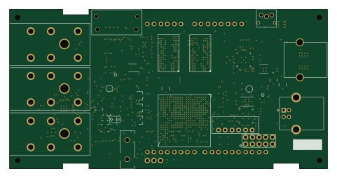 FPGA
Zynq
juliancoy
120 × 60 mm295 partsMIT75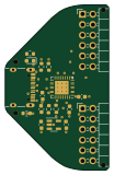
PmodUsbUlpi
twam
25 × 40 mm18 parts2LNo license15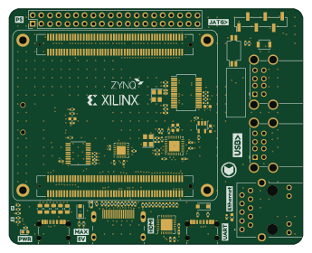 FPGA
ZYNQ7020 Development Board
dj140
86 × 69 mm121 parts4LNo license2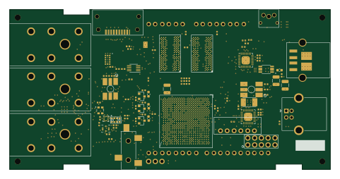 FPGA
NeuraCore
NeuraCoreTech
120 × 60 mm295 parts8LNo license0
The USB3320 in open source designs
The gallery holds 4 open source boards using the USB3320 from 4 GitHub repositories; a typical one measures about 103 × 60 mm and carries around 208 components.
67% use four copper layers or more, and 25% carry an open source license.
The most starred is ZynqPCB by juliancoy.
Parts used alongside the USB3320
Microcontrollers on boards using the USB3320
What boards using the USB3320 are built for
USB3320: common questions
Where can I find a USB3320 reference design?
Each of the 4 boards on this page is a real design using the USB3320. Open one to see how it is wired up, with the full BOM, a render of the layout and links to its KiCad files.
What parts are used alongside the USB3320?
The APDS-9960, LSM6DSLTR, S25FL256SAGNFI001, TLV320AIC3104 and TPS51200DRCR appear in the most repositories here.
Which microcontrollers do boards using the USB3320 use?
Most are built on FPGA (3).
How big is a typical board using the USB3320?
The median is 103 × 60 mm, and 33% are two-layer designs.
What is the most popular open source board using the USB3320?
By GitHub stars, ZynqPCB by juliancoy, with 75 stars.
Can I simulate one of these boards using the USB3320 before building it?
Yes. HardLabs turns a board's netlist and BOM into a working simulation, so you can boot and test firmware against it with no hardware on your desk.