
21 open source boards using the AXP209
Real designs built with the AXP209, from public GitHub projects: a quick way to see how others power, decouple and connect it. Each board comes with its KiCad files, full parts list and a render — and you can simulate its firmware on HardLabs.
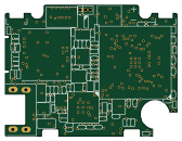
FunKey-S-Hardware
FunKey-Project
42 × 32 mm212 partsCC-BY-4.0123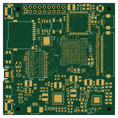
NekoInk
zephray
60 × 60 mm231 parts4LCERN-OHL-P-2.0106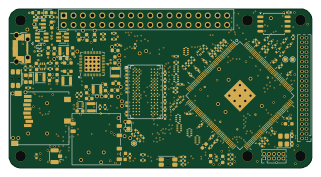
Sbc allwinner a13
vd-rd
80 × 42 mm163 parts4LNo license38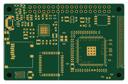
Sbc allwinner v3s
66 × 42 mm155 parts4LNo license22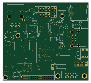
Netholi
expeyes
80.2 × 72.3 mm210 partsNo license18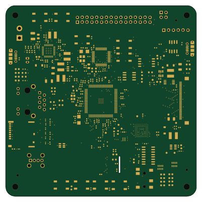 STM32
OzzyBoard
vbalsan
100 × 100 mm278 parts4LGPL-2.04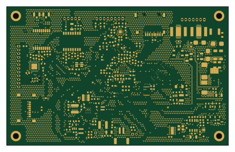 STM32
ControlPanelV3S
bartkepl
120 × 75 mm300 parts4LMIT0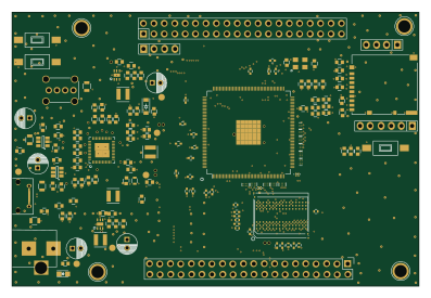
Gc3
masahirosuzuka
99.2 × 66.8 mm191 parts6LNo license0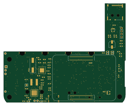 AVR/Arduino
HAT CM4 183
ConnectBox
105.6 × 86.1 mm161 parts6LNo license0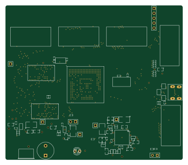
A10-sbc
91.9 × 80.3 mm180 partsNo license18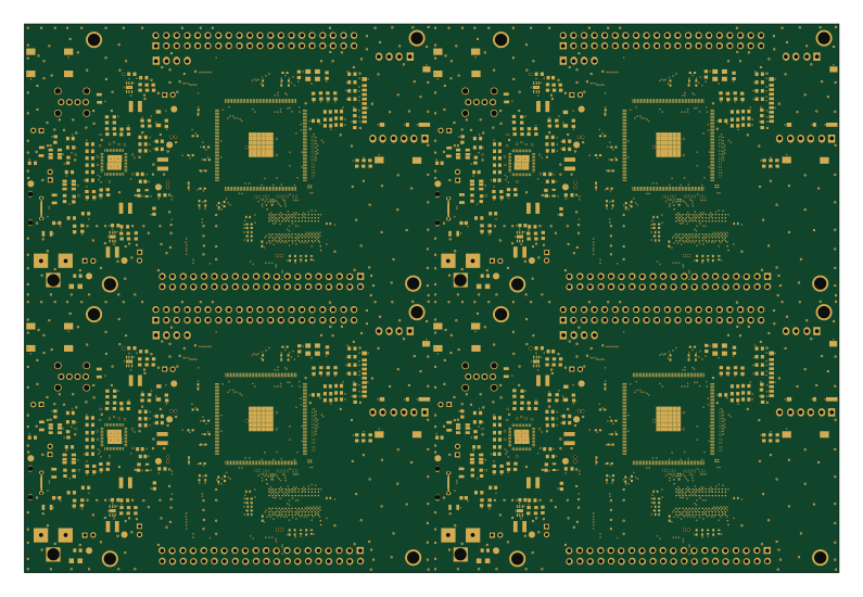
Gc3 panelized
198.4 × 133.6 mm191 parts6LNo license0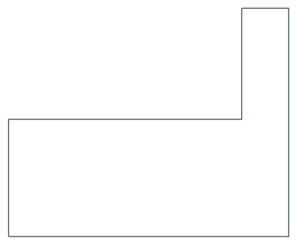 AVR/Arduino
HAT CM4 DRC 1
105.6 × 86.1 mm147 parts6LNo license0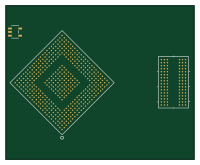
Slarm zero awa20.1
jlywxy
49.9 × 40.7 mm124 parts4LGPL-2.00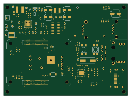 AVR/Arduino
ConnectBox HAT using RPi CM4
105 × 78 mm130 parts4LNo license0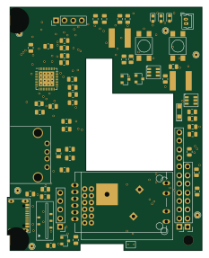
HAT ver 7
57.4 × 71.6 mm72 parts2LNo license0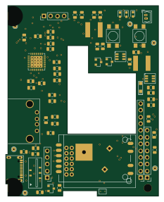
HAT ver 8
57.4 × 71.6 mm72 parts2LNo license0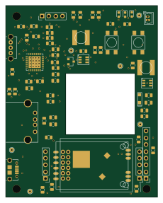
HAT ver 5.1
56.6 × 71.6 mm68 parts2LNo license0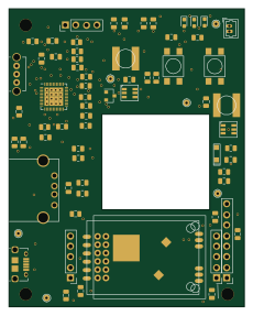
HAT ver 6.0
56.6 × 71.6 mm68 parts2LNo license0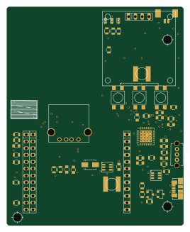
NanoPi NEO USB HAT - Version 4.7
66 × 81.6 mm63 parts2LNo license0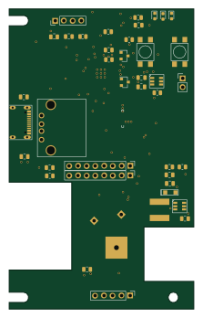
ConnectBox HAT 8
53.7 × 87 mm60 parts4LNo license0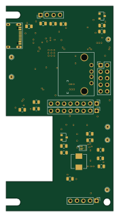
ConnectBox HAT-A
41.6 × 79.2 mm54 parts4LNo license0
How designs wire the AXP209
Read from the KiCad layouts of 10 open source designs, one per repository: what each pin of the AXP209 connects to, and the resistors, capacitors and other passives placed on it.
- The LDO24IN pin has a capacitor to GND on 10 of 10 designs, most often 10 µF (then 100 nF).
- The APS pin has a capacitor to GND on 10 of 10 designs, most often 10 µF (then 220 nF).
- The BIAS pin has a resistor to GND on 10 of 10 designs, most often 200 kΩ.
- The VREF pin has a capacitor to GND on 10 of 10 designs, most often 1 µF (then 2.2 µF).
| Pin | Connected to | Parts on the pin |
|---|---|---|
| SDApin 1 | Connected to: A connector 50%, the microcontroller 30%, V3S 20% |
|
| SCKpin 2 | Connected to: A connector 50%, the microcontroller 30%, V3S 20% |
|
| GPIO3pin 3 | Connected to: Not connected 90% | — |
| N_OEpin 4 | Connected to: Signal 70% · GND 30% |
|
| GPIO2pin 5 | Connected to: Not connected 90% | — |
| VIN2pin 7 | Connected to: AP61100 20%, MCP1640CH 20% · VOUT 20% |
|
| LX2pin 8 | Connected to: Signal 80% |
|
| PGND2pin 9 | Connected to: GND 90% | — |
| DCDC2pin 10 | Connected to: 1.2V 80% |
|
| LDO4pin 11 | Connected to: 3.3V 50% · a signal 50% |
|
| LDO2pin 12 | Connected to: 3V 80% · a signal 20% | — |
| LDO24INpin 13 | Connected to: AP61100 20%, MCP1640CH 20% · 3.3V 20% |
|
| VIN3pin 14 | Connected to: AP61100 20%, MCP1640CH 20% · VOUT 20% |
|
| LX3pin 15 | Connected to: Signal 80% |
|
| PGND3pin 16 | Connected to: GND 90% | — |
| DCDC3pin 17 | Connected to: 1.2V 80% |
|
| GPIO1pin 18 | Connected to: Not connected 70% · a signal 30% | — |
| GPIO0pin 19 | Connected to: A connector 20% · not connected 30% |
|
| APSpin 21 | Connected to: AP61100 20%, MCP1640CH 20% · VOUT 20% |
|
| AGNDpin 22 | Connected to: GND 100% | — |
| BIASpin 23 | Connected to: Signal 100% |
|
| VREFpin 24 | Connected to: Signal 90% |
|
| PWROKpin 25 | Connected to: V3S 20%, a connector 20% |
|
| VINTpin 26 | Connected to: VINT 60% · a signal 40% |
|
| LDO1pin 28 | Connected to: 3.3V 80% | — |
| DC3SETpin 29 | Connected to: Not connected 70% · VOUT 20% |
|
| BACKUPpin 30 | Connected to: Not connected 80% · a signal 20% | — |
| VBUSpin 31 | Connected to: 5V 70% · not connected 20% |
|
| ACINpin 32, 33 | Connected to: A connector 40% · not connected 20% · 5V 30% |
|
| IPSOUTpin 34, 35 | Connected to: AP61100 20%, MCP1640CH 20% · VOUT 20% |
|
| TSpin 37 | Connected to: A connector 30% |
|
| BATpin 38, 39 | Connected to: VBAT 70% · not connected 30% |
|
| LDO3INpin 40 | Connected to: AP61100 20%, MCP1640CH 20% · 3.3V 20% |
|
| LDO3pin 41 | Connected to: 3.3V 50% · a signal 50% |
|
| BATSENSEpin 42 | Connected to: VBAT 70% · not connected 30% |
|
| CHSENSEpin 43 | Connected to: Signal 70% · not connected 30% |
|
| VIN1pin 44 | Connected to: AP61100 20%, MCP1640CH 20% · VOUT 20% |
|
| LX1pin 45 | Connected to: Signal 70% · not connected 30% |
|
| PGND1pin 46 | Connected to: GND 90% | — |
| PWRONpin 47 | Connected to: Signal 100% |
|
6 more pins vary from design to design. Connections count pins, parts count designs; values in brackets are how many parts had that value. Designs read include FunKey-S-Hardware by FunKey-Project, NekoInk by zephray, Sbc allwinner a13 by vd-rd and Sbc allwinner v3s by vd-rd.
The AXP209 in open source designs
The gallery holds 21 open source boards using the AXP209 from 10 GitHub repositories; a typical one measures about 66 × 72.3 mm and carries around 155 components.
72% use four copper layers or more, and 24% carry an open source license.
The most starred is FunKey-S-Hardware by FunKey-Project.
Parts used alongside the AXP209
Microcontrollers on boards using the AXP209
What boards using the AXP209 are built for
AXP209: common questions
Where can I find a AXP209 reference design?
Each of the 21 boards on this page is a real design using the AXP209. Open one to see how it is wired up, with the full BOM, a render of the layout and links to its KiCad files.
How is the AXP209 LDO24IN pin connected?
The LDO24IN pin has a capacitor to GND on 10 of 10 designs, most often 10 µF (then 100 nF). Counted from the KiCad layouts of 10 open source designs using the AXP209.
How is the AXP209 APS pin connected?
The APS pin has a capacitor to GND on 10 of 10 designs, most often 10 µF (then 220 nF). Counted from the KiCad layouts of 10 open source designs using the AXP209.
What resistor goes on the AXP209 BIAS pin?
The BIAS pin has a resistor to GND on 10 of 10 designs, most often 200 kΩ. Counted from the KiCad layouts of 10 open source designs using the AXP209.
What parts are used alongside the AXP209?
The SY8088AAC, USBLC6-2P6, V3S, W25Q128JVS and A13 appear in the most repositories here.
Which microcontrollers do boards using the AXP209 use?
Most are built on AVR/Arduino (3) and STM32 (2).
How big is a typical board using the AXP209?
The median is 66 × 72.3 mm, and 28% are two-layer designs.
What is the most popular open source board using the AXP209?
By GitHub stars, FunKey-S-Hardware by FunKey-Project, with 123 stars.
Can I simulate one of these boards using the AXP209 before building it?
Yes. HardLabs turns a board's netlist and BOM into a working simulation, so you can boot and test firmware against it with no hardware on your desk.