
17 open source boards using the LM5164DDA
Real designs built with the LM5164DDA, from public GitHub projects: a quick way to see how others power, decouple and connect it. Each board comes with its KiCad files, full parts list and a render — and you can simulate its firmware on HardLabs.
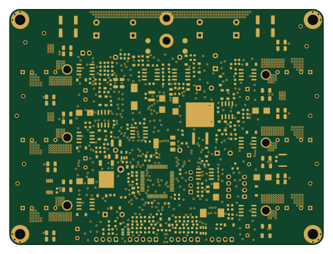 ESP32
Bobbycar-FOC-hardware
bobbycar-graz
120 × 90 mm293 parts2LNo license23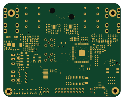
HPM6P41 BB
Alipay1
100 × 80.3 mm276 parts4LMIT14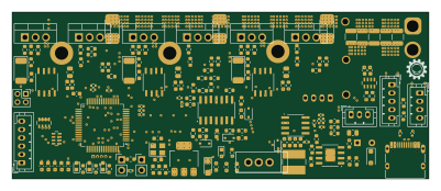 STM32
VESX
NormalHuman-Anything
100 × 40 mm177 parts4LCERN-OHL-W-2.03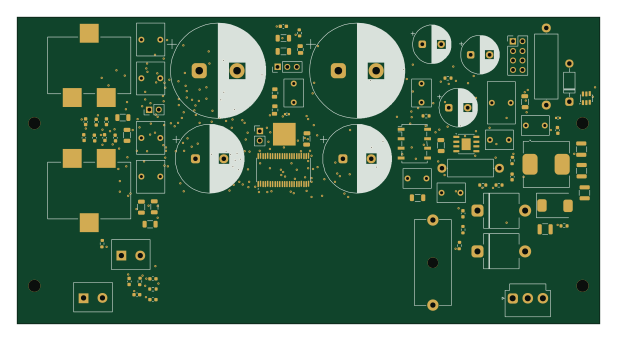
PS28 CORE B - SELECTED - CASE FIT UNMEASURED
bernardopg
154 × 81 mm203 parts4LNo license1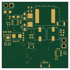 STM32
CNC Buck
JasonClock
60 × 60 mm78 parts4LNo license1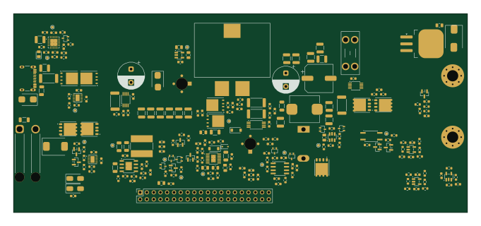
USB-C PD bench supply - power board
GarryBGoode
170 × 74.5 mm237 parts4LNo license0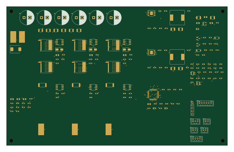 STM32
Bldc
kobertkirk
190 × 120 mm163 parts4LNo license0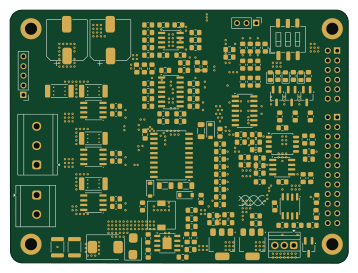
E foc
embedded-pro
89.4 × 66.9 mm154 parts2LNo license0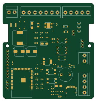 ESP32
Citofono vintage
michele88pg
81 × 85 mm61 parts2LCC-BY-SA-4.00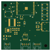 ESP32
KleverLogger
charclo
50 × 50 mm61 parts4LNo license0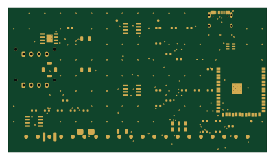 ESP32
Tesla dual lin rev a
lakewoodphone
100 × 56 mm45 parts4LNo license0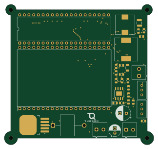
TURQON-DPS-01
Onaensar
80.9 × 75.5 mm32 parts2LNo license0- schematic only · 14 parts
AURORA-vehicle control platform
sharon169961
14 partsNo license0 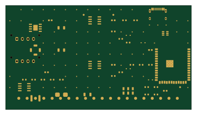 ESP32
Unrouted
100 × 56 mm45 parts4LNo license0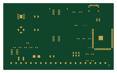 ESP32
Autoroute probe
100 × 60 mm17 parts4LNo license0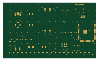 ESP32
Tesla dual lin rev a routed
100 × 60 mm17 parts4LNo license0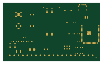 ESP32
Vx fpNoZone
100 × 60 mm17 parts4LNo license0
How designs wire the LM5164DDA
Read from the KiCad layouts of 12 open source designs, one per repository: what each pin of the LM5164DDA connects to, and the resistors, capacitors and other passives placed on it.
- The FB pin has a resistor to GND on 11 of 11 designs, most often 50 kΩ (then 10 kΩ).
- The BST pin has a series capacitor on 11 of 11 designs, most often 2.2 nF (then 100 nF).
- The SW pin has a series capacitor on 11 of 11 designs, most often 2.2 nF (then 100 nF).
- The SW pin has a inductor on 11 of 11 designs, most often 68 µH (then 33 µH).
| Pin | Connected to | Parts on the pin |
|---|---|---|
| GNDpin 1 | Connected to: GND 92% | — |
| VINpin 2 | Connected to: VIN 75% · a signal 17% |
|
| EN/UVLOpin 3 | Connected to: Signal 67% · VIN 33% |
|
| RONpin 4 | Connected to: Signal 91% |
|
| FBpin 5 | Connected to: Signal 100% |
|
| PGOODpin 6 | Connected to: Not connected 73% · a signal 27% | — |
| BSTpin 7 | Connected to: Signal 100% |
|
| SWpin 8 | Connected to: Signal 100% |
|
| EPpin 9 | Connected to: GND 100% | — |
Connections count pins, parts count designs; values in brackets are how many parts had that value. Designs read include Bobbycar-FOC-hardware by bobbycar-graz, HPM6P41 BB by Alipay1, VESX by NormalHuman-Anything and PS28 CORE B - SELECTED - CASE FIT UNMEASURED by bernardopg.
The LM5164DDA in open source designs
The gallery holds 17 open source boards using the LM5164DDA from 13 GitHub repositories; a typical one measures about 100 × 63.4 mm and carries around 61 components.
75% use four copper layers or more, and 18% carry an open source license.
The most starred is Bobbycar-FOC-hardware by bobbycar-graz.
Parts used alongside the LM5164DDA
What boards using the LM5164DDA are built for
LM5164DDA: common questions
Where can I find a LM5164DDA reference design?
Each of the 17 boards on this page is a real design using the LM5164DDA. Open one to see how it is wired up, with the full BOM, a render of the layout and links to its KiCad files.
What resistor goes on the LM5164DDA FB pin?
The FB pin has a resistor to GND on 11 of 11 designs, most often 50 kΩ (then 10 kΩ). Counted from the KiCad layouts of 12 open source designs using the LM5164DDA.
How is the LM5164DDA BST pin connected?
The BST pin has a series capacitor on 11 of 11 designs, most often 2.2 nF (then 100 nF). Counted from the KiCad layouts of 12 open source designs using the LM5164DDA.
How is the LM5164DDA SW pin connected?
The SW pin has a series capacitor on 11 of 11 designs, most often 2.2 nF (then 100 nF). Counted from the KiCad layouts of 12 open source designs using the LM5164DDA.
What parts are used alongside the LM5164DDA?
The AMS1117-3.3, AP2112K-3.3, LM1117DT-3.3, TJA1051T-3 and TLV9062 appear in the most repositories here.
Which microcontrollers do boards using the LM5164DDA use?
Most are built on ESP32 (8) and STM32 (3).
How big is a typical board using the LM5164DDA?
The median is 100 × 63.4 mm, and 25% are two-layer designs.
What is the most popular open source board using the LM5164DDA?
By GitHub stars, Bobbycar-FOC-hardware by bobbycar-graz, with 23 stars.
Can I simulate one of these boards using the LM5164DDA before building it?
Yes. HardLabs turns a board's netlist and BOM into a working simulation, so you can boot and test firmware against it with no hardware on your desk.