
11 open source boards using the MC6850
Real designs built with the MC6850, from public GitHub projects: a quick way to see how others power, decouple and connect it. Each board comes with its KiCad files, full parts list and a render — and you can simulate its firmware on HardLabs.
- schematic only · 84 parts
Nanocomp6809
breadboardinglabs
84 partsApache-2.024 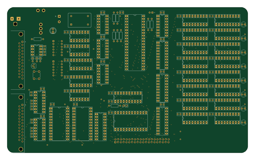
Fennec6800
ChartreuseK
218 × 131.9 mm113 parts2LBSD-3-Clause20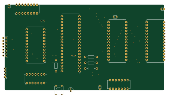
MOUSE
mkeller0815
138.4 × 74.9 mm21 parts2LMIT14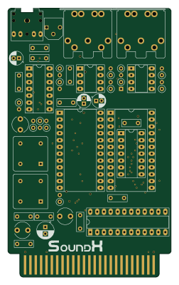
SoundX
SukkoPera
60.8 × 100 mm44 parts2LNo license8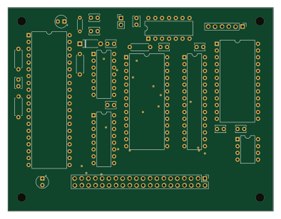 PIC
Sbc6802
ryu10
98.3 × 75.6 mm29 parts2LNo license6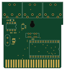
Midiskirt
barzamin
61.9 × 66.7 mm28 parts2LNo license1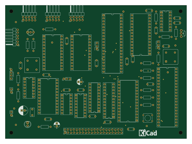
MUTIF09 Single Board Computer
ja1umi
155 × 114 mm68 parts2LMIT10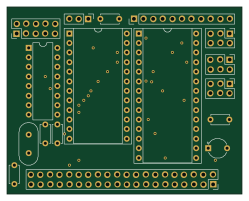
MicroKit09Serial
electrickery
62.2 × 49.5 mm17 parts2LNo license1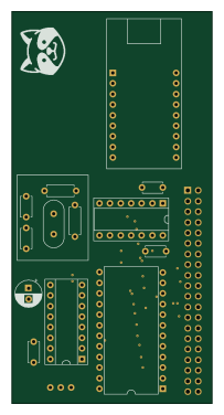
8 16 computer 2 serial card
halfburnttoast
48 × 94 mm14 parts2LNo license21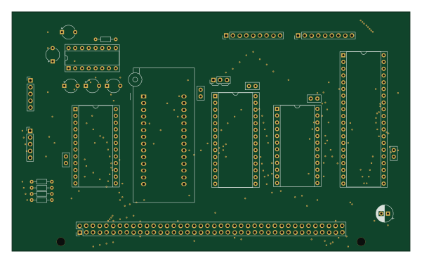
MemoryAndPeripherals
daveho
150 × 90 mm28 partsNo license19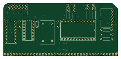
RC6802 Serial Chicken
tebl
99.1 × 45.7 mm17 parts2LCERN-OHL-1.26
How designs wire the MC6850
Read from the KiCad layouts of 10 open source designs, one per repository: what each pin of the MC6850 connects to, and the resistors, capacitors and other passives placed on it.
- The DCD pin is tied to GND on 8 of 10 designs (not connected on 2).
- The RTS pin is left unconnected on 6 of 10 designs (a signal on 4).
- The CS0 pin is tied to VCC on 6 of 10 designs (a signal on 3).
- The CS1 pin is tied to VCC on 6 of 10 designs (a signal on 3).
| Pin | Connected to | Parts on the pin |
|---|---|---|
| VSSpin 1 | Connected to: GND 100% | — |
| RTSpin 5 | Connected to: Not connected 60% · a signal 40% | — |
| TX_DATApin 6 | Connected to: A connector 40% |
|
| IRQpin 7 | Connected to: A connector 40% · not connected 20% |
|
| CS0pin 8 | Connected to: VCC 60% · a signal 30% | — |
| CS1pin 10 | Connected to: VCC 60% · a signal 30% | — |
| VCCpin 12 | Connected to: 5V 100% |
|
| DCDpin 23 | Connected to: GND 80% · not connected 20% | — |
| CTSpin 24 | Connected to: GND 60% · a signal 30% | — |
15 more pins vary from design to design. Connections count pins, parts count designs; values in brackets are how many parts had that value. Designs read include 8 16 computer 2 serial card by halfburnttoast, Fennec6800 by ChartreuseK, MemoryAndPeripherals by daveho and MOUSE by mkeller0815.
The MC6850 in open source designs
The gallery holds 11 open source boards using the MC6850 from 11 GitHub repositories; a typical one measures about 98.7 × 82.8 mm and carries around 28 components.
100% are two-layer designs, the rest use four layers or more, and 45% carry an open source license.
The most starred is Nanocomp6809 by breadboardinglabs.
Parts used alongside the MC6850
Microcontrollers on boards using the MC6850
What boards using the MC6850 are built for
MC6850: common questions
Where can I find a MC6850 reference design?
Each of the 11 boards on this page is a real design using the MC6850. Open one to see how it is wired up, with the full BOM, a render of the layout and links to its KiCad files.
How is the MC6850 DCD pin connected?
The DCD pin is tied to GND on 8 of 10 designs (not connected on 2). Counted from the KiCad layouts of 10 open source designs using the MC6850.
How is the MC6850 RTS pin connected?
The RTS pin is left unconnected on 6 of 10 designs (a signal on 4). Counted from the KiCad layouts of 10 open source designs using the MC6850.
How is the MC6850 CS0 pin connected?
The CS0 pin is tied to VCC on 6 of 10 designs (a signal on 3). Counted from the KiCad layouts of 10 open source designs using the MC6850.
What parts are used alongside the MC6850?
The 74LS04, 74LS138, 28C256, 74HCT74 and 74LS00 appear in the most repositories here.
Which microcontrollers do boards using the MC6850 use?
Most are built on PIC (1).
How big is a typical board using the MC6850?
The median is 98.7 × 82.8 mm, and 100% are two-layer designs.
What is the most popular open source board using the MC6850?
By GitHub stars, Nanocomp6809 by breadboardinglabs, with 24 stars.
Can I simulate one of these boards using the MC6850 before building it?
Yes. HardLabs turns a board's netlist and BOM into a working simulation, so you can boot and test firmware against it with no hardware on your desk.