
13 open source boards using the TPS26600PWPR
Real designs built with the TPS26600PWPR, from public GitHub projects: a quick way to see how others power, decouple and connect it. Each board comes with its KiCad files, full parts list and a render — and you can simulate its firmware on HardLabs.
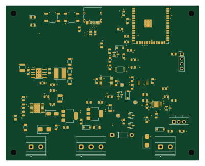 ESP32
Chatgpt astra test2
fredriknk
100 × 80 mm90 parts4LMIT3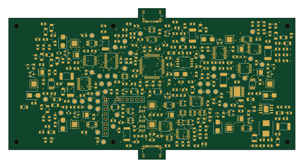 STM32
Hub
Bruhdows
148 × 78 mm309 parts4LNo license1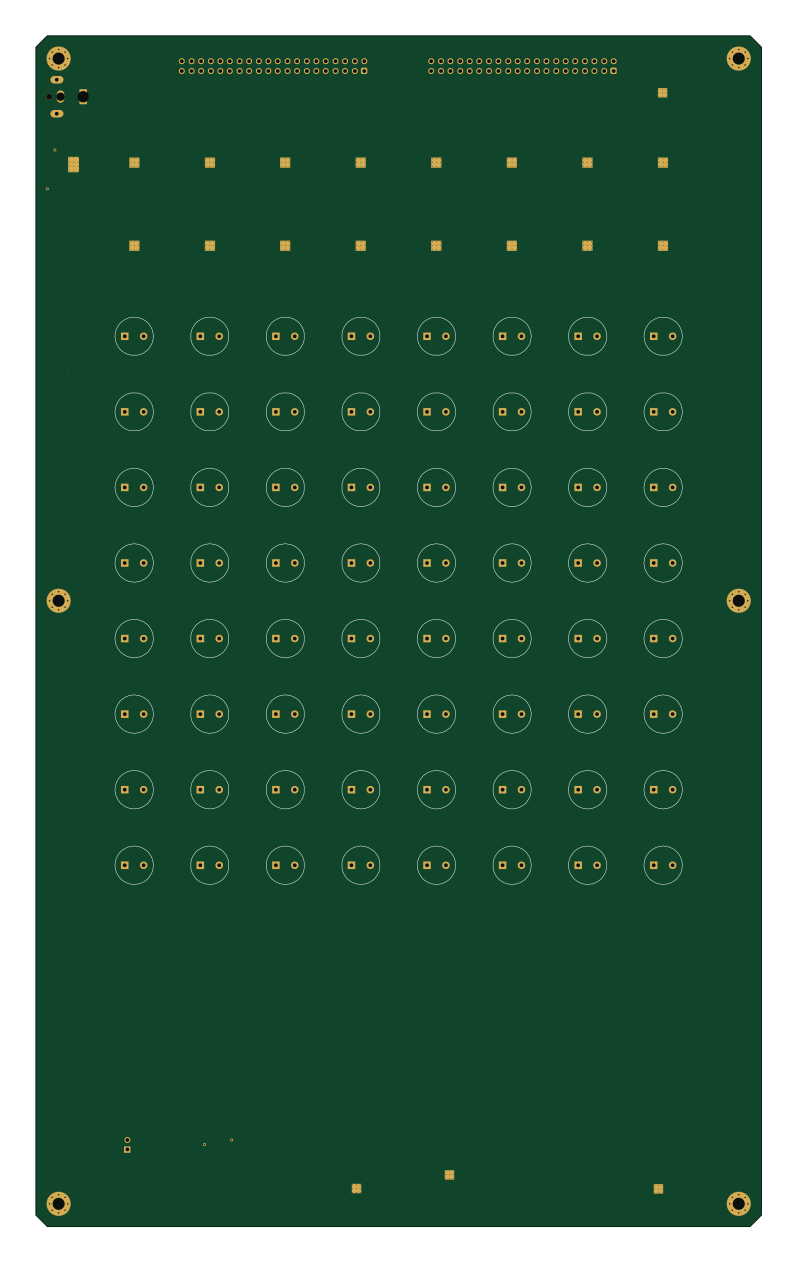
Aesa
tieziyun
192 × 315.1 mm2040 parts4LNo license0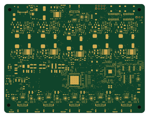 Raspberry Pi
Iasis
hydazz
130 × 100 mm636 parts6LApache-2.00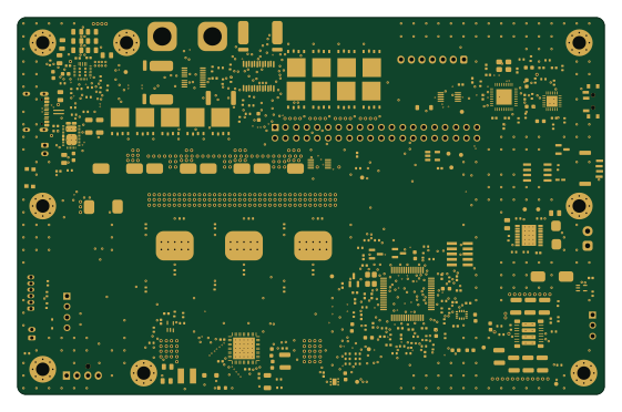 STM32
Atlas drive
AtlasAutoware
140 × 90 mm377 parts6LNo license0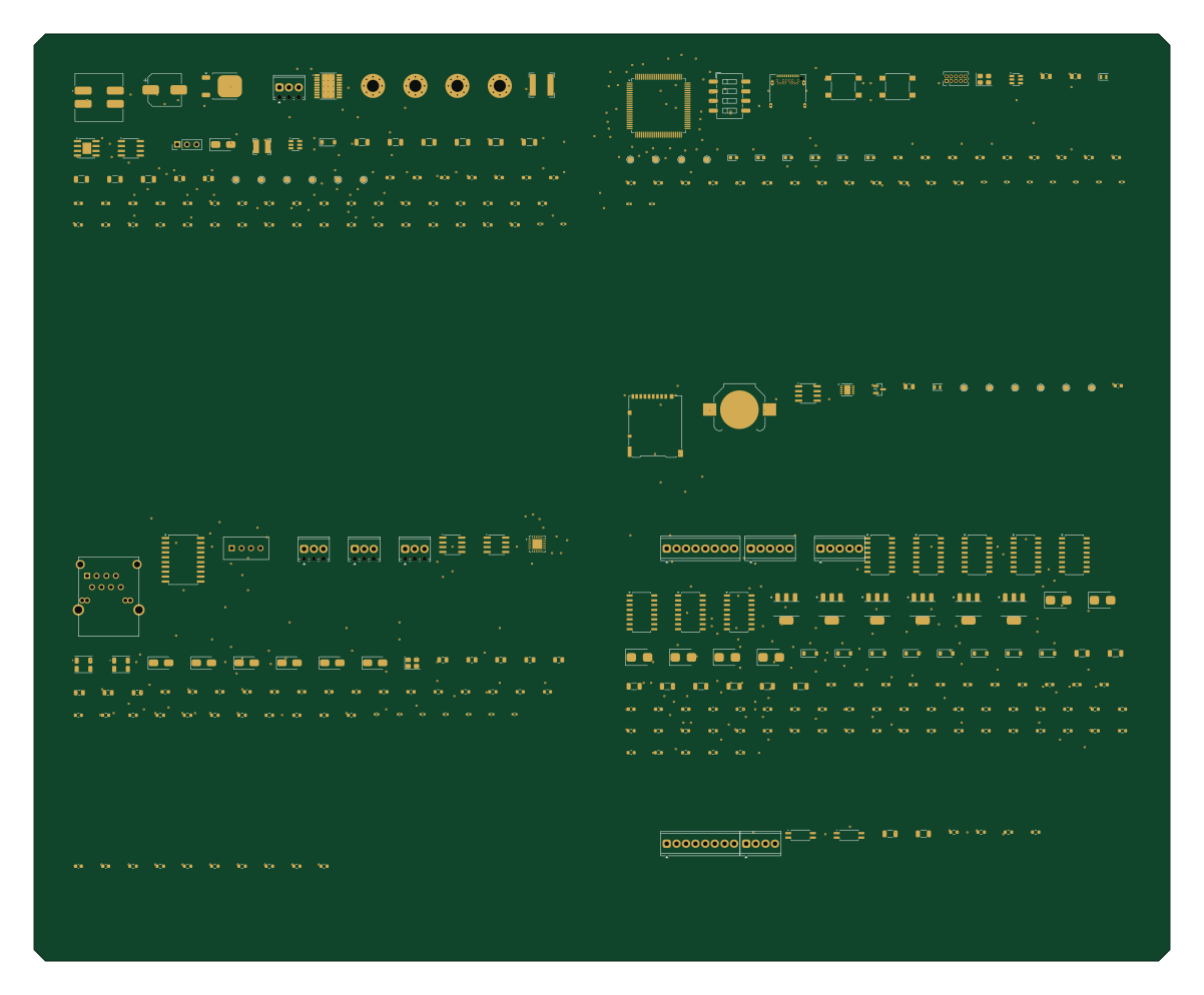 STM32
Akd safe source gateway
zinedkahitaf-lang
300 × 245 mm290 parts6LNo license0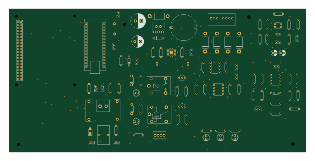 AVR/Arduino
Design-Assembly and-Commissioning of a-GreenPHY-Based-EVSE-Signalling and-Communication-Emulator
Shriniketpk2124
250 × 121 mm101 parts2LNo license0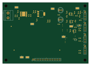 ESP32
Sensor Interface & Power Management Board for ESP32
AJC938
90 × 64 mm52 parts2LMIT0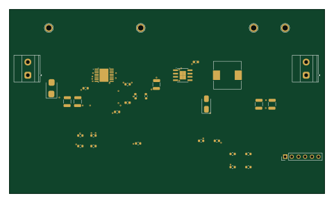
Protected buck
Shanshan3133
120 × 70 mm31 parts2LNo license0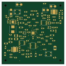 WCH CH32/CH55x
Tile
68 × 68 mm109 parts4LNo license1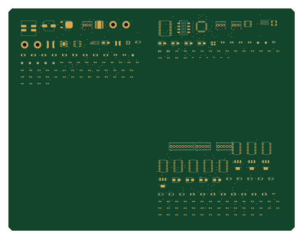 STM32
Akd safe interlock node
245 × 190 mm182 parts6LNo license0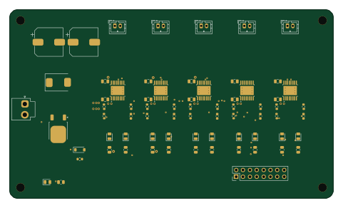
Power hub
kartben
120 × 70 mm70 parts2LApache-2.00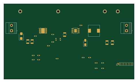
Protected buck unrouted
120 × 70 mm31 parts2LNo license0
How designs wire the TPS26600PWPR
Read from the KiCad layouts of 10 open source designs, one per repository: what each pin of the TPS26600PWPR connects to, and the resistors, capacitors and other passives placed on it.
- The NC_13 pin is left unconnected on 10 of 10 designs.
- The NC_4 pin is left unconnected on 9 of 10 designs.
- The UVLO_3 pin has a series resistor on 7 of 10 designs, most often 10 kΩ (then 40.2 kΩ).
- The OUT_15 pin has a capacitor to GND on 7 of 10 designs, most often 100 nF (then 10 µF).
| Pin | Connected to | Parts on the pin |
|---|---|---|
| IN_1pin 1 | Connected to: VIN_FUSED 70% · a signal 30% | — |
| IN_2pin 2 | Connected to: VIN_FUSED 70% · a signal 30% | — |
| UVLO_3pin 3 | Connected to: Signal 80% |
|
| NC_4pin 4 | Connected to: Not connected 90% | — |
| OVP_5pin 5 | Connected to: Signal 80% · GND 20% |
|
| MODE_6pin 6 | Connected to: Signal 50% · not connected 30% · GND 20% |
|
| RTN_8pin 8 | Connected to: Signal 60% · GND 40% |
|
| GND_9pin 9 | Connected to: GND 100% | — |
| IMON_10pin 10 | Connected to: Not connected 70% · a signal 30% | — |
| ILIM_11pin 11 | Connected to: Signal 90% |
|
| DVDT_12pin 12 | Connected to: Signal 90% |
|
| NC_13pin 13 | Connected to: Not connected 100% | — |
| FLT_14pin 14 | Connected to: Signal 50% · not connected 40% |
|
| OUT_15pin 15 | Connected to: A connector 20% · 5V 20% |
|
| OUT_16pin 16 | Connected to: A connector 20% · 5V 20% |
|
| RTN_17pin 17 | Connected to: Signal 60% · GND 40% |
|
1 more pin varies from design to design. Connections count pins, parts count designs; values in brackets are how many parts had that value. Designs read include Chatgpt astra test2 by fredriknk, Hub by Bruhdows, Sensor Interface & Power Management Board for ESP32 by AJC938 and Atlas drive by AtlasAutoware.
The TPS26600PWPR in open source designs
The gallery holds 13 open source boards using the TPS26600PWPR from 10 GitHub repositories; a typical one measures about 130 × 80 mm and carries around 109 components.
62% use four copper layers or more, and 31% carry an open source license.
The most starred is Chatgpt astra test2 by fredriknk.
Parts used alongside the TPS26600PWPR
Microcontrollers on boards using the TPS26600PWPR
What boards using the TPS26600PWPR are built for
TPS26600PWPR: common questions
Where can I find a TPS26600PWPR reference design?
Each of the 13 boards on this page is a real design using the TPS26600PWPR. Open one to see how it is wired up, with the full BOM, a render of the layout and links to its KiCad files.
How is the TPS26600PWPR NC_13 pin connected?
The NC_13 pin is left unconnected on 10 of 10 designs. Counted from the KiCad layouts of 10 open source designs using the TPS26600PWPR.
How is the TPS26600PWPR NC_4 pin connected?
The NC_4 pin is left unconnected on 9 of 10 designs. Counted from the KiCad layouts of 10 open source designs using the TPS26600PWPR.
What resistor goes on the TPS26600PWPR UVLO_3 pin?
The UVLO_3 pin has a series resistor on 7 of 10 designs, most often 10 kΩ (then 40.2 kΩ). Counted from the KiCad layouts of 10 open source designs using the TPS26600PWPR.
What parts are used alongside the TPS26600PWPR?
The SN74AHCT1G125DBVR, TMUX1511PWR, USBLC6-2SC6, STM32F405RGT6 and TPS259470LRPWR appear in the most repositories here.
Which microcontrollers do boards using the TPS26600PWPR use?
Most are built on STM32 (4), ESP32 (2), AVR/Arduino (1) and WCH CH32/CH55x (1).
How big is a typical board using the TPS26600PWPR?
The median is 130 × 80 mm, and 38% are two-layer designs.
What is the most popular open source board using the TPS26600PWPR?
By GitHub stars, Chatgpt astra test2 by fredriknk, with 3 stars.
Can I simulate one of these boards using the TPS26600PWPR before building it?
Yes. HardLabs turns a board's netlist and BOM into a working simulation, so you can boot and test firmware against it with no hardware on your desk.