
38 open source boards using the LM2596S-ADJ
Real designs built with the LM2596S-ADJ, from public GitHub projects: a quick way to see how others power, decouple and connect it. Each board comes with its KiCad files, full parts list and a render — and you can simulate its firmware on HardLabs.
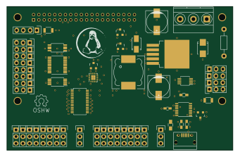
96boards robomezzi
mwelling
85 × 54 mm112 parts4LCC-BY-SA-4.06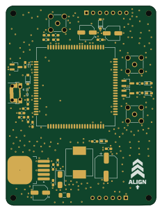
Stm32-sim7600-gps-4g lte anti theft tracker
MohamedKhay154
57.1 × 76 mm56 parts4LNo license2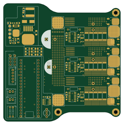 STM32
McQueen
0BitsnBytes
100.5 × 101.5 mm137 parts6LGPL-3.01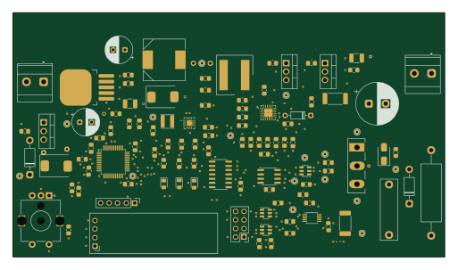 STM32
Flyback-Driver
Operationorange01
128 × 72.5 mm115 parts4LNo license1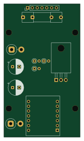
ESP32-C5-OBD2-Scanner
Aleksei327
40 × 70 mm36 parts2LCC-BY-NC-4.01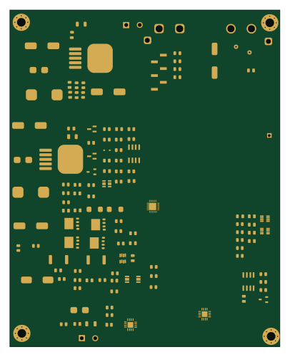
DSP-Regulator-RevC
Phil-CIA
100 × 125 mm226 parts2LNo license0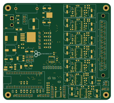 AVR/Arduino
Truss
practable
114.3 × 102.9 mm198 parts2LAGPL-3.00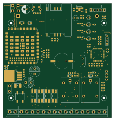 STM32
STM32 IOT GATEWAY
RiddheshVeling
99 × 105 mm154 parts2LNo license0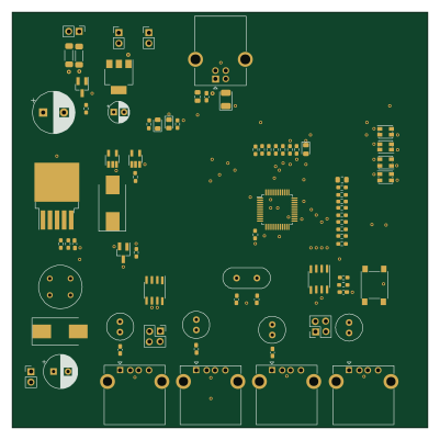
USB 2.0 Smart 4 port hub on GL852
shworker
100 × 100 mm100 parts2LNo license0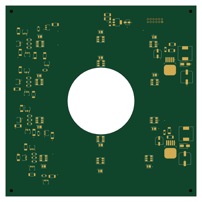
Fly High throughput - optogenetics
open-neuroscience
170 × 170 mm94 parts2LGPL-3.00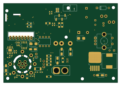 RP2040/RP2350
DIY T12 iron
anshchawla521
97 × 67 mm90 parts2LNo license0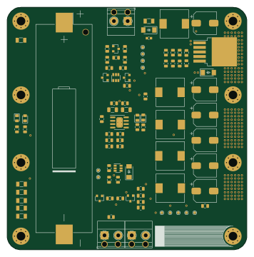
Li ion-UPS-24V
Gosmann
88.9 × 89.9 mm82 parts2LNo license0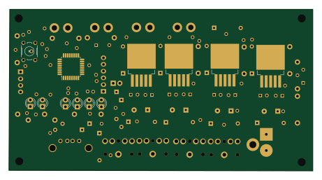 AVR/Arduino
Rilis1
mekatronik-achmadi
115.1 × 61 mm60 parts2LNo license0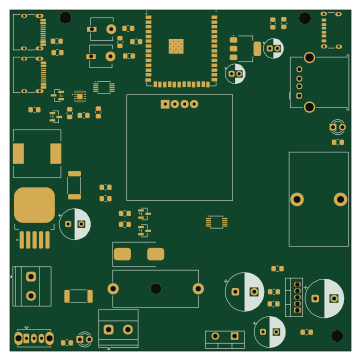 ESP32
PowerDistributionBoard
AnmolS-EE
90 × 90 mm58 parts4LMIT0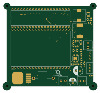
TURQON-DPS-01
Onaensar
80.9 × 75.5 mm32 parts2LNo license0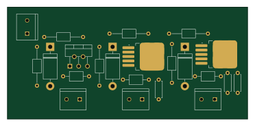
Buck conveter
UltraInstinct21
92.7 × 43.2 mm22 parts2LNo license0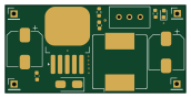
BC--LM2596--ADJ
sujitkumar05-pcb
43 × 21 mm15 parts2LNo license0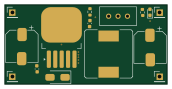
Kicad buck converter
ddennis18
43 × 21 mm15 parts2LNo license0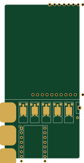 AVR/Arduino
ChessRobotArm
BujoreanuVlad
40.3 × 82.5 mm12 parts2LNo license0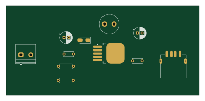
Solar USB Buck Converter
jiroegbu-eng
99.9 × 46.5 mm11 parts2LNo license0- schematic only · 37 partsESP32
RoboArm
9Akshit1
37 partsMIT0 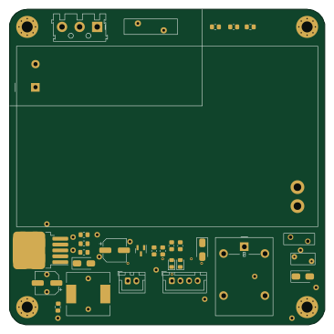
IoT Power Supply
atoomnetmarc
91.4 × 91.4 mm29 parts2LApache-2.014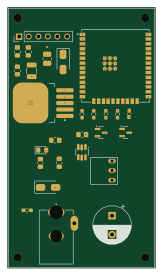 ESP32
BaseChipOnly
ZonatedCord
39.1 × 68.9 mm21 parts2LCC-BY-NC-4.01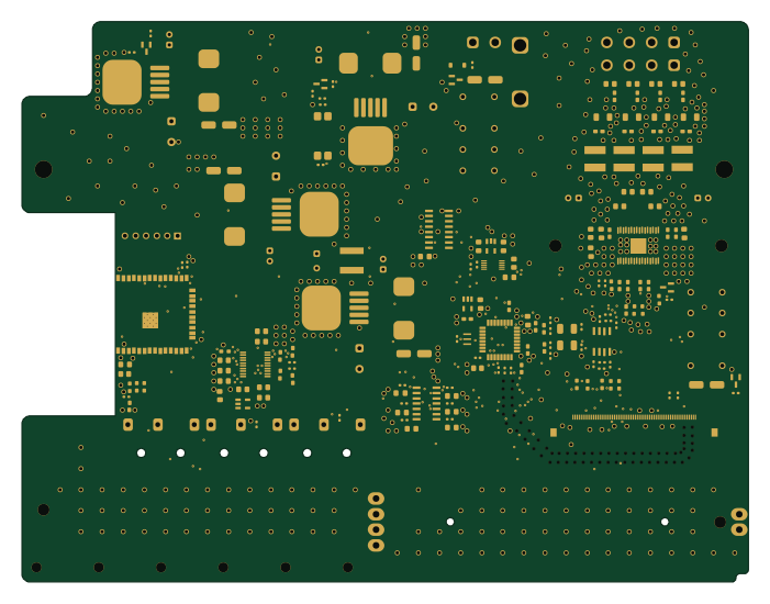 ESP32
Systemboard
adrianhelfer
175 × 135 mm193 parts4LNo license0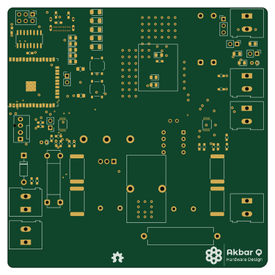 ESP32
MPPT-Controller
akbar-q
99 × 99 mm96 parts4LNo license0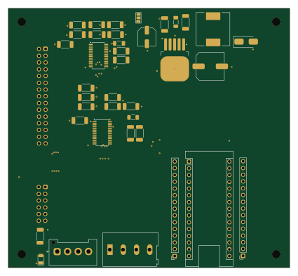 AVR/Arduino
Fly High throughput - main board
106 × 97.5 mm39 parts2LGPL-3.00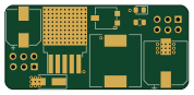
Ivegotdapower elec board fille
PhenixRobotik
44.5 × 20.3 mm36 parts2LNo license0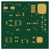
Voltage Regulator seneryo Y (Input 15V)
manyetox
50 × 50 mm22 parts2LNo license0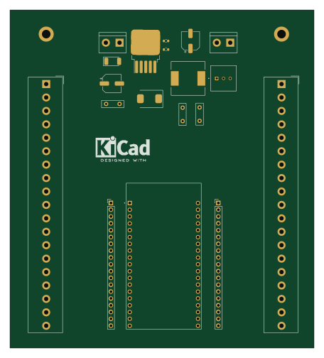 ESP32
Tarea Final
ThaysNivar
113 × 125.7 mm19 parts2LNo license0- schematic only · 92 parts
ACU5EV SoM Carrier Board
raonslab2
92 parts6LNo license0 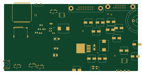 STM32
Hw cpu
andreili
150 × 75.4 mm100 parts2LGPL-3.066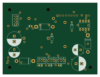
TDP3 VOLTAGE REG w BUCK
saadmaziz
85.5 × 65 mm43 parts2LMIT0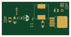
Main
ilkercosar
60 × 30 mm16 parts4LNo license0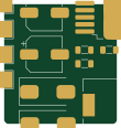
FPC
kholia
27.1 × 28.7 mm9 parts2LNo license23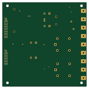
Right Panel PCB 1
85 × 85 mm25 parts2LNo license0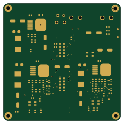
DSP-Regulator-RevB
100 × 100 mm88 parts2LNo license0
How designs wire the LM2596S-ADJ
Read from the KiCad layouts of 33 open source designs, one per repository: what each pin of the LM2596S-ADJ connects to, and the resistors, capacitors and other passives placed on it.
- The OUT pin has a inductor on 31 of 33 designs, most often 33 µH (then 47 µH).
- The FB pin has a resistor to GND on 26 of 33 designs, most often 1 kΩ (then 1.5 kΩ).
- The ON/OFF pin is tied to GND on 26 of 33 designs (a signal on 6).
- The VIN pin has a decoupling capacitor on 18 of 33 designs, most often 100 nF (then 470 µF).
| Pin | Connected to | Parts on the pin |
|---|---|---|
| VINpin 1 | Connected to: VIN 58% · a signal 42% |
|
| OUTpin 2 | Connected to: Signal 94% |
|
| GNDpin 3 | Connected to: GND 94% | — |
| FBpin 4 | Connected to: Signal 88% |
|
| ON/OFFpin 5 | Connected to: GND 79% · a signal 18% | — |
Connections count pins, parts count designs; values in brackets are how many parts had that value. Designs read include Hw cpu by andreili, FPC by kholia, IoT Power Supply by atoomnetmarc and 96boards robomezzi by mwelling.
The LM2596S-ADJ in open source designs
The gallery holds 38 open source boards using the LM2596S-ADJ from 35 GitHub repositories; a typical one measures about 90.7 × 75.5 mm and carries around 41 components.
76% are two-layer designs, the rest use four layers or more, and 29% carry an open source license.
The most starred is Hw cpu by andreili.
Parts used alongside the LM2596S-ADJ
Microcontrollers on boards using the LM2596S-ADJ
What boards using the LM2596S-ADJ are built for
LM2596S-ADJ: common questions
Where can I find a LM2596S-ADJ reference design?
Each of the 38 boards on this page is a real design using the LM2596S-ADJ. Open one to see how it is wired up, with the full BOM, a render of the layout and links to its KiCad files.
How is the LM2596S-ADJ OUT pin connected?
The OUT pin has a inductor on 31 of 33 designs, most often 33 µH (then 47 µH). Counted from the KiCad layouts of 33 open source designs using the LM2596S-ADJ.
What resistor goes on the LM2596S-ADJ FB pin?
The FB pin has a resistor to GND on 26 of 33 designs, most often 1 kΩ (then 1.5 kΩ). Counted from the KiCad layouts of 33 open source designs using the LM2596S-ADJ.
How is the LM2596S-ADJ ON/OFF pin connected?
The ON/OFF pin is tied to GND on 26 of 33 designs (a signal on 6). Counted from the KiCad layouts of 33 open source designs using the LM2596S-ADJ.
What parts are used alongside the LM2596S-ADJ?
The AMS1117-3.3, ADS1115IDGS, Arduino_Nano_v3.x, INA226 and LM2596S-5 appear in the most repositories here.
Which microcontrollers do boards using the LM2596S-ADJ use?
Most are built on ESP32 (7), AVR/Arduino (4), STM32 (4) and RP2040/RP2350 (1).
How big is a typical board using the LM2596S-ADJ?
The median is 90.7 × 75.5 mm, and 76% are two-layer designs.
What is the most popular open source board using the LM2596S-ADJ?
By GitHub stars, Hw cpu by andreili, with 66 stars.
Can I simulate one of these boards using the LM2596S-ADJ before building it?
Yes. HardLabs turns a board's netlist and BOM into a working simulation, so you can boot and test firmware against it with no hardware on your desk.