
76 open source boards using the TL082
Real designs built with the TL082, from public GitHub projects: a quick way to see how others power, decouple and connect it. Each board comes with its KiCad files, full parts list and a render — and you can simulate its firmware on HardLabs.
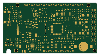 PIC
Pslab hardware
fossasia
99 × 53.3 mm187 parts4LApache-2.01.7k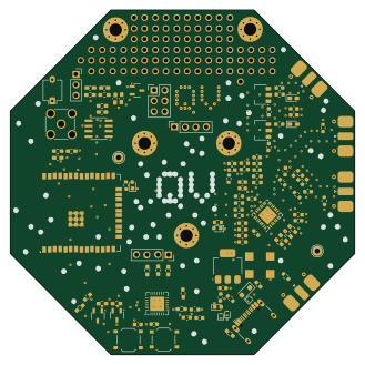 ESP32
Uncut Gem
QuantumVillage
82.1 × 82.1 mm110 parts2LAGPL-3.0197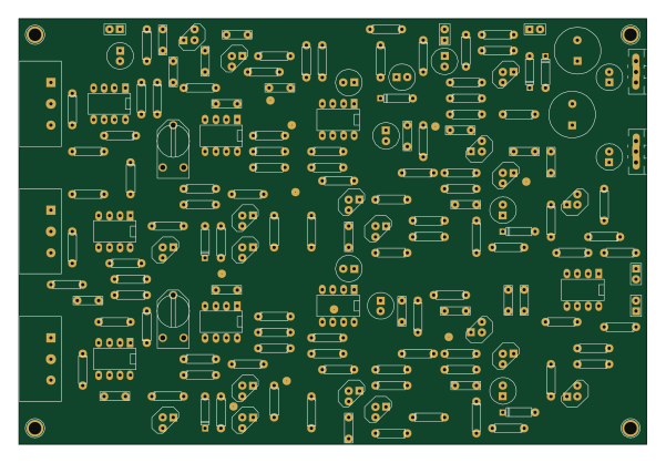
Juno chorus clone
gligli
149.9 × 101.6 mm172 parts2LGPL-3.057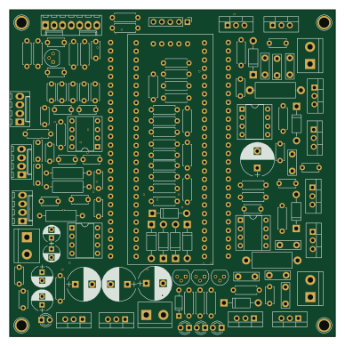
Psoc5power
profdc9
96.8 × 97 mm133 parts2LNo license56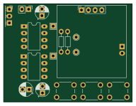 RISC-V
Osillyscope etchable
tvlad1234
48 × 36.5 mm29 parts2LMIT29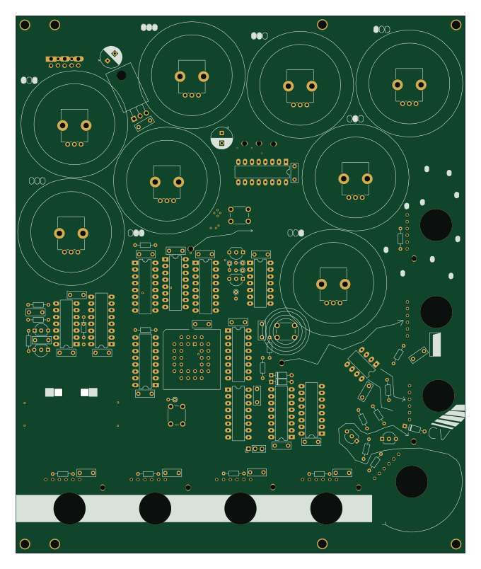
Random Jazz Generator
telec16
167.8 × 200.6 mm126 parts2LNo license16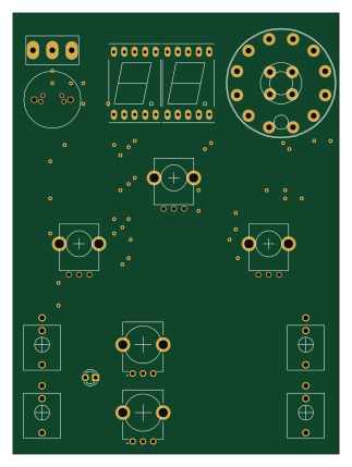
Eurorack spinfx
grappendorf
79 × 107 mm79 parts2LNo license16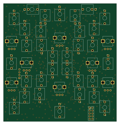 STM32
Allcolours
microresearch
101.3 × 106.2 mm246 partsNo license15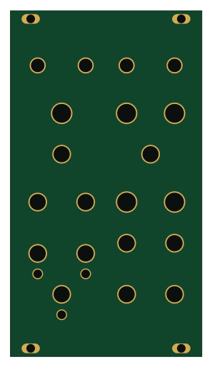 AVR/Arduino
Tarbleming
MiguelDeTrool
71 × 128.5 mm91 parts2LCustom license14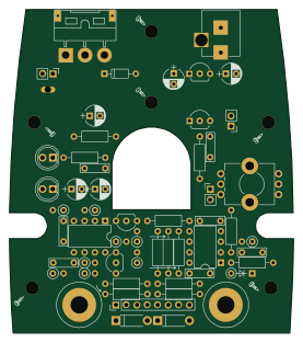
Esr meter rev b
4x1md
68.7 × 78.2 mm55 parts2LMIT14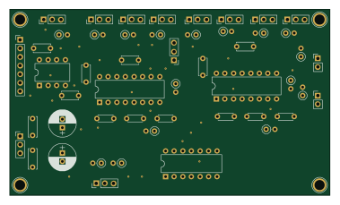
3310ADSR
hermflink
94.5 × 55 mm50 parts2LGPL-3.011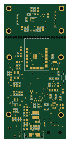 ESP32
ONLY ECG fix
tregatti-tech
55.9 × 121.3 mm147 parts2LNo license9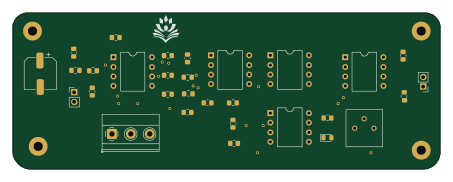
Digital-Stethoscope
darknight2163
113.1 × 41.3 mm30 parts2LNo license9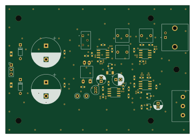
Electronics uldosc
mpinese
100 × 70 mm54 parts2LNo license6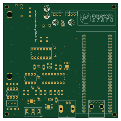
Potenciostato
potenciostato
100 × 100 mm57 parts2LGPL-3.03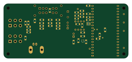 ESP32
ARG OSCI HARDWARE
ArgOsciProyect
113 × 50 mm56 parts2LCustom license3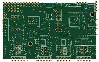 AVR/Arduino
Curry2
etf-lth
82 × 50.1 mm167 partsNo license2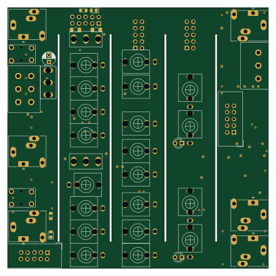
Kicad LFO 1 2
promesoft
100 × 100 mm147 parts2LMIT2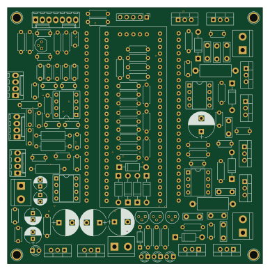
Psoc5power
iduwhux
96.8 × 97 mm133 parts2LNo license1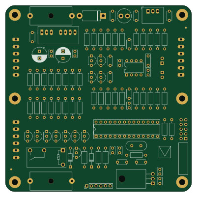 AVR/Arduino
Modulo-Two ARINC-429 Converter
morris6
100 × 100 mm97 parts2LNo license1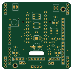
Dreamster board
dreamster
62 × 60 mm50 parts2LNo license1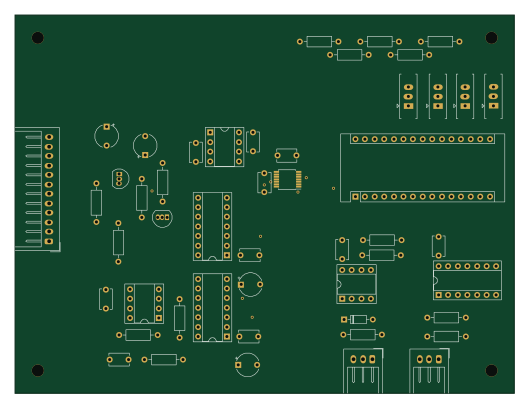 AVR/Arduino
DAC-for minimoog
gkaxowns9
132 × 100 mm49 parts2LNo license1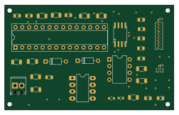 AVR/Arduino
Digital-Stethoscope
Ashley-Ann-Benoy
63 × 39 mm33 parts2LNo license1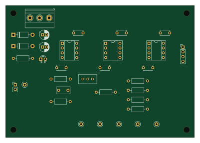
Memristor emulator
sofia-kirilov
100 × 70 mm33 parts2LNo license1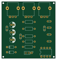
Analog overdrive guitar pedal
elia-pia
47 × 49.5 mm22 parts2LGPL-3.01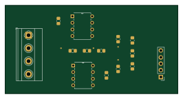
Hsb amcd sose2025-5
ryanromeodev
66.5 × 34 mm12 parts2LApache-2.01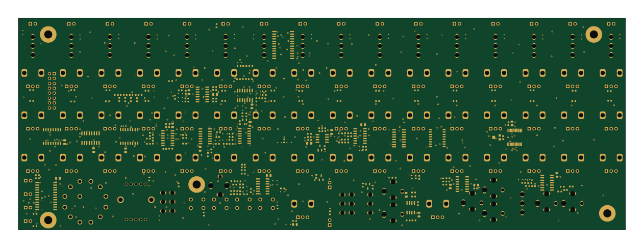
SoundLab16StepSequencer
JakeBoothy
314.9 × 110 mm348 parts4LNo license0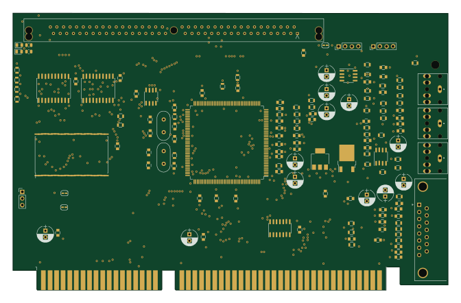
Guspnp
tuutuum
167.6 × 106.8 mm148 parts2LNo license0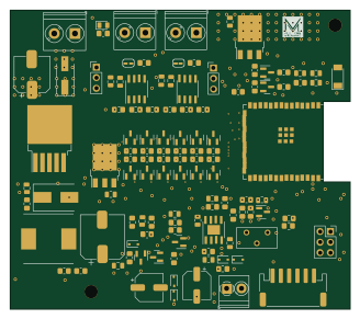 ESP32
HT 485
lucafaccin
82 × 72.2 mm115 parts2LNo license0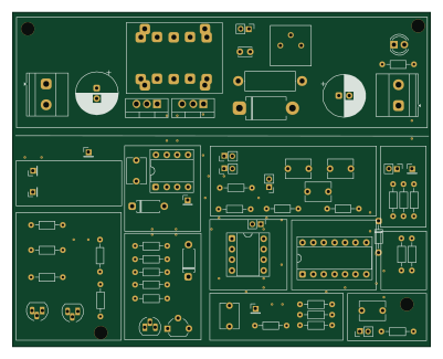
Circuito regulador conmutado de tensión
Seba-SL
100 × 80 mm66 parts2LNo license0
Bachelor thesis
dario0603
99 × 99 mm57 parts2LNo license0
Kicad project
Phelma-BE2
50 × 30 mm55 parts2LGPL-3.00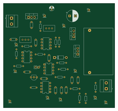
Buck realimentada2
Balta-Etche-FIUBA
95 × 89 mm54 parts2LNo license0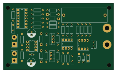
Analog-ESR-Meter
glydeck
100 × 60 mm44 parts2LCC0-1.00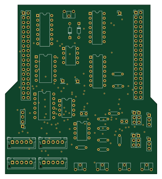
LaserGameSystem
VectorSpaceHQ
82 × 91.2 mm42 parts2LGPL-3.00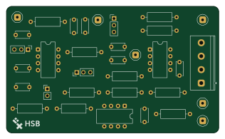
ANSreport
adityadabas1008
79 × 47 mm31 parts2LNo license0
How designs wire the TL082
Read from the KiCad layouts of 50 open source designs, one per repository: what each pin of the TL082 connects to, and the resistors, capacitors and other passives placed on it.
- The - pins have a series resistor on 43 of 50 designs, most often 10 kΩ (then 1 kΩ).
- The OUT pin has a series resistor on 36 of 50 designs, most often 1 kΩ (then 10 kΩ).
- Pin 7 has a series resistor on 35 of 50 designs, most often 10 kΩ (then 1 kΩ).
- The OUT pin has a series capacitor on 26 of 50 designs, most often 100 nF (then 470 pF).
| Pin | Connected to | Parts on the pin |
|---|---|---|
| OUTpin 1 | Connected to: Signal 94% |
|
| -pin 2, 6 | Connected to: Signal 90% |
|
| +pin 3, 5 | Connected to: Signal 70% · GND 23% |
|
| V-pin 4 | Connected to: -12V 52% · GND 28% · a signal 18% |
|
| Pin 7 | Connected to: A connector 22% |
|
| V+pin 8 | Connected to: 12V 86% |
|
Connections count pins, parts count designs; values in brackets are how many parts had that value. Designs read include Pslab hardware by fossasia, Uncut Gem by QuantumVillage, Juno chorus clone by gligli and Psoc5power by profdc9.
The TL082 in open source designs
The gallery holds 76 open source boards using the TL082 from 52 GitHub repositories; a typical one measures about 85.7 × 91.2 mm and carries around 56 components.
96% are two-layer designs, the rest use four layers or more, and 30% carry an open source license.
The most starred is Pslab hardware by fossasia.
Parts used alongside the TL082
Microcontrollers on boards using the TL082
What boards using the TL082 are built for
TL082: common questions
Where can I find a TL082 reference design?
Each of the 76 boards on this page is a real design using the TL082. Open one to see how it is wired up, with the full BOM, a render of the layout and links to its KiCad files.
What resistor goes on the TL082 - pin?
The - pins have a series resistor on 43 of 50 designs, most often 10 kΩ (then 1 kΩ). Counted from the KiCad layouts of 50 open source designs using the TL082.
What resistor goes on the TL082 OUT pin?
The OUT pin has a series resistor on 36 of 50 designs, most often 1 kΩ (then 10 kΩ). Counted from the KiCad layouts of 50 open source designs using the TL082.
What resistor goes on the TL082 pin 7?
Pin 7 has a series resistor on 35 of 50 designs, most often 10 kΩ (then 1 kΩ). Counted from the KiCad layouts of 50 open source designs using the TL082.
What parts are used alongside the TL082?
The L7805, L7812, MCP4922, TL072 and TL084 appear in the most repositories here.
Which microcontrollers do boards using the TL082 use?
Most are built on AVR/Arduino (6), ESP32 (6), STM32 (6) and PIC (3).
How big is a typical board using the TL082?
The median is 85.7 × 91.2 mm, and 96% are two-layer designs.
What is the most popular open source board using the TL082?
By GitHub stars, Pslab hardware by fossasia, with 1,700 stars.
Can I simulate one of these boards using the TL082 before building it?
Yes. HardLabs turns a board's netlist and BOM into a working simulation, so you can boot and test firmware against it with no hardware on your desk.