
43 open source boards using the ATTINY85-20PU
Real designs built with the ATTINY85-20PU, from public GitHub projects: a quick way to see how others power, decouple and connect it. Each board comes with its KiCad files, full parts list and a render — and you can simulate its firmware on HardLabs.
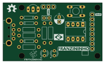 AVR/Arduino
Franzininho diy board
Franzininho
51.1 × 30 mm19 partsCC-BY-SA-4.0114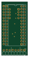 AVR/Arduino
C64-Switchless-Multi-Kernal-27C256-adapter
bwack
22.2 × 46.4 mm14 parts2LCERN-OHL-1.2112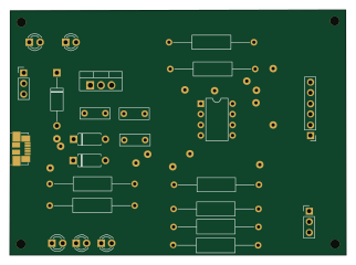 AVR/Arduino
PCB ATtiny85
tidus747
80.3 × 58.6 mm25 parts2LGPL-3.012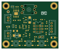 AVR/Arduino
EasyLight
ModischFabrications
50.2 × 41.3 mm41 parts2LCERN-OHL-S-2.08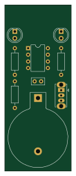 AVR/Arduino
Kicon19-blinky
ShawnHymel
25.4 × 63.5 mm9 parts2LNo license4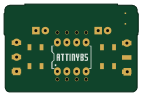 AVR/Arduino
MCore Mixtape
8BitMixtape
35.5 × 23.2 mm23 parts2LNo license3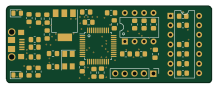 AVR/Arduino
Shiny avr
tibordp
54.4 × 20.3 mm39 parts4LBSD-2-Clause2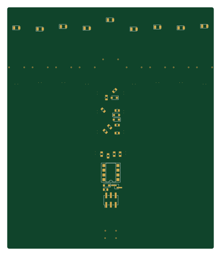 AVR/Arduino
Menorah
azzeloof
111.6 × 130.3 mm30 parts2LNo license2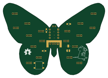 AVR/Arduino
Butterfly hw
mignon-p
93.1 × 65.5 mm26 parts2LCC-BY-SA-4.02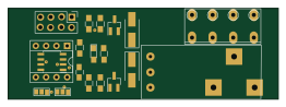 AVR/Arduino
Relay
anno73
65.5 × 22 mm19 parts2LNo license1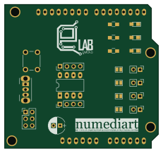 AVR/Arduino
Creactif electroLAB
Vincent-Stragier
57.6 × 53.9 mm18 parts2LMIT1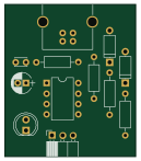 AVR/Arduino
Handbrake
StarGate01
31.8 × 36.8 mm12 parts2LGPL-2.01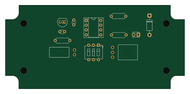 AVR/Arduino
Dell alienware psu spoofer
ttfsapps
93.6 × 43.7 mm12 parts2LNo license1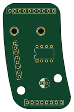 AVR/Arduino
Attiny programmer
barafael
35.4 × 55.6 mm7 parts2LNo license1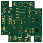 AVR/Arduino
ToothEater-HW-THT
BlackbirdStandalone
44 × 44 mm32 parts2LCERN-OHL-S-2.00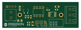 AVR/Arduino
A2R-100k
mgiesen
68 × 23 mm20 parts2LNo license0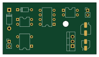 AVR/Arduino
Odoconv
movatica
51 × 27.9 mm16 parts2LNo license0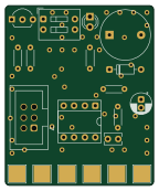 AVR/Arduino
Openscex carrier
gufranco
35.6 × 43.1 mm14 parts2LMIT0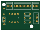 AVR/Arduino
Phenakistiscope
jfraire
35.6 × 26.7 mm10 parts2LCC0-1.00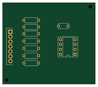 AVR/Arduino
Svi728keyboardreset
arttu76
48 × 42 mm10 parts2LNo license0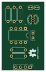 AVR/Arduino
Attiny85 I2C RGB LED v2.0
rsedak
22.4 × 36.4 mm9 parts2LCustom license0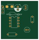 AVR/Arduino
Autostop killer
kubiq
33 × 34 mm8 parts2LMIT0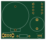 AVR/Arduino
ATtinyTorture
flynn-28
37.2 × 31.8 mm6 parts2LGPL-3.00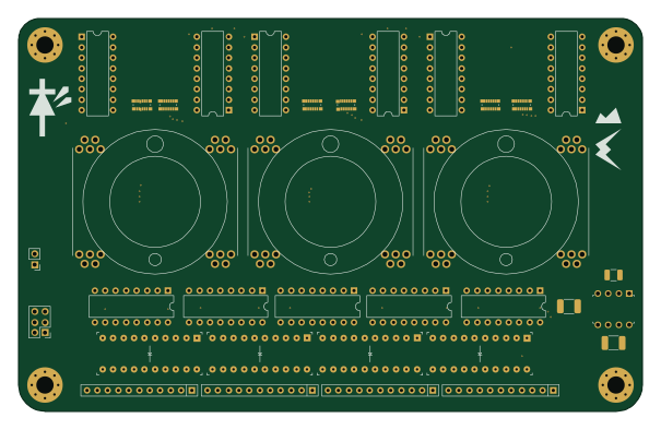 AVR/Arduino
LED Panel
Plasmarobo
151.1 × 95.3 mm34 parts2LCC-BY-NC-4.01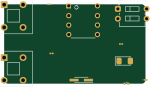 AVR/Arduino
Practice1
m3llo0n
37.4 × 21 mm11 parts2LNo license1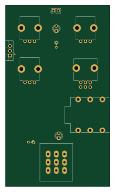 AVR/Arduino
Chorus
rabidaudio
54.6 × 95.3 mm70 parts2LNo license0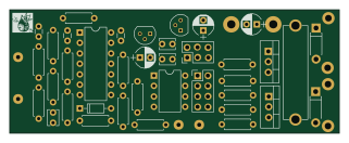 AVR/Arduino
ReleaseBoard
AvalonROV
80 × 30 mm43 parts2LNo license0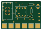 AVR/Arduino
Openscex mini
35.6 × 25.1 mm6 parts2LMIT0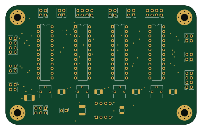 AVR/Arduino
SSD Panel
104.1 × 64.8 mm30 parts2LCC-BY-NC-4.01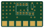 AVR/Arduino
Openscex bare
35.6 × 21.6 mm3 parts2LMIT0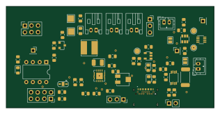 AVR/Arduino
Measure Battery Level
node9909
79 × 38.6 mm57 parts2LNo license10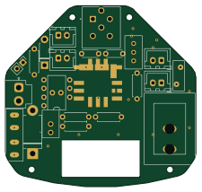 AVR/Arduino
Integrated Power Board
MUNAKATA-EPC
56 × 53.2 mm25 parts2LMIT3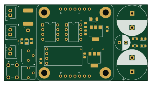 AVR/Arduino
Pwm esc
ChipCE
75.2 × 40.1 mm29 parts2LGPL-3.02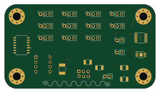 AVR/Arduino
Analog Panel
80 × 44.5 mm24 parts2LCC-BY-NC-4.01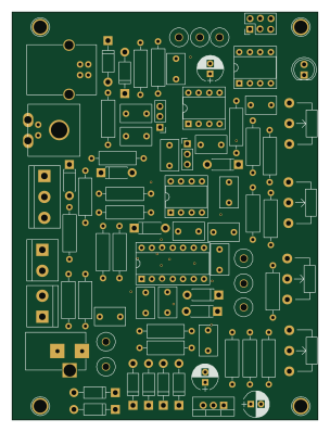 AVR/Arduino
Lineinterrupter
profdc9
74.4 × 99.3 mm85 parts2LNo license56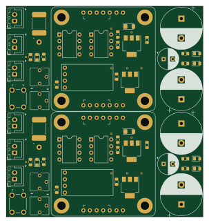 AVR/Arduino
Pwm esc panelized
75.3 × 80.6 mm29 parts2LGPL-3.02
How designs wire the ATTINY85-20PU
Read from the KiCad layouts of 35 open source designs, one per repository: what each pin of the ATTINY85-20PU connects to, and the resistors, capacitors and other passives placed on it.
- The AREF/PB0 pin has a series resistor on 14 of 35 designs, most often 100 Ω (then 68 Ω).
- The VCC pin has a decoupling capacitor on 14 of 35 designs, most often 100 nF (then 10 µF).
| Pin | Connected to | Parts on the pin |
|---|---|---|
| XTAL1/PB3pin 2 | Connected to: A connector 37% · not connected 17% |
|
| XTAL2/PB4pin 3 | Connected to: A connector 23% · not connected 20% |
|
| GNDpin 4 | Connected to: GND 91% | — |
| AREF/PB0pin 5 | Connected to: A connector 54% |
|
| PB1pin 6 | Connected to: A connector 46% · not connected 17% |
|
| PB2pin 7 | Connected to: A connector 54% |
|
| VCCpin 8 | Connected to: 5V 77% · a signal 23% |
|
1 more pin varies from design to design. Connections count pins, parts count designs; values in brackets are how many parts had that value. Designs read include Franzininho diy board by Franzininho, C64-Switchless-Multi-Kernal-27C256-adapter by bwack, Charlieplex 3x3 by rjwalters and Interrupter by profdc9.
The ATTINY85-20PU in open source designs
The gallery holds 43 open source boards using the ATTINY85-20PU from 35 GitHub repositories; a typical one measures about 51.1 × 43.7 mm and carries around 19 components.
98% are two-layer designs, the rest use four layers or more, and 49% carry an open source license.
The most starred is Franzininho diy board by Franzininho.
Parts used alongside the ATTINY85-20PU
Microcontrollers on boards using the ATTINY85-20PU
What boards using the ATTINY85-20PU are built for
ATTINY85-20PU: common questions
Where can I find a ATTINY85-20PU reference design?
Each of the 43 boards on this page is a real design using the ATTINY85-20PU. Open one to see how it is wired up, with the full BOM, a render of the layout and links to its KiCad files.
What resistor goes on the ATTINY85-20PU AREF/PB0 pin?
The AREF/PB0 pin has a series resistor on 14 of 35 designs, most often 100 Ω (then 68 Ω). Counted from the KiCad layouts of 35 open source designs using the ATTINY85-20PU.
What decoupling capacitors do designs use on the ATTINY85-20PU VCC pin?
The VCC pin has a decoupling capacitor on 14 of 35 designs, most often 100 nF (then 10 µF). Counted from the KiCad layouts of 35 open source designs using the ATTINY85-20PU.
What parts are used alongside the ATTINY85-20PU?
The L7809, LM339, LM7805_TO220 and NE555 appear in the most repositories here.
Which microcontrollers do boards using the ATTINY85-20PU use?
Most are built on AVR/Arduino (43).
How big is a typical board using the ATTINY85-20PU?
The median is 51.1 × 43.7 mm, and 98% are two-layer designs.
What is the most popular open source board using the ATTINY85-20PU?
By GitHub stars, Franzininho diy board by Franzininho, with 114 stars.
Can I simulate one of these boards using the ATTINY85-20PU before building it?
Yes. HardLabs turns a board's netlist and BOM into a working simulation, so you can boot and test firmware against it with no hardware on your desk.