
24 open source boards using the INA180A2
Real designs built with the INA180A2, from public GitHub projects: a quick way to see how others power, decouple and connect it. Each board comes with its KiCad files, full parts list and a render — and you can simulate its firmware on HardLabs.
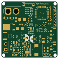
Power Board
ZhuYanzhen1
50 × 50 mm88 parts2LAGPL-3.057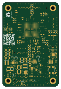
Gmm
GMM-7550
50 × 75 mm240 parts6LNo license36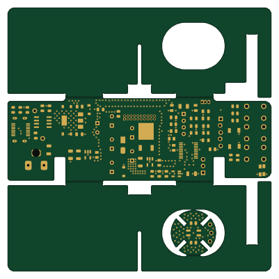 STM32
PCB-reflow solder table
DerSpatz
100 × 100 mm77 parts2LMIT14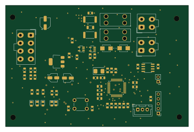 STM32
PDU
OpenSkyHawk
96.6 × 63.9 mm67 parts2LCC-BY-NC-4.03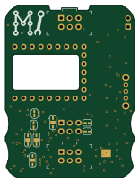 RP2040/RP2350
SAO Demo Controller
ageppert
38.1 × 50.8 mm50 parts2LMIT3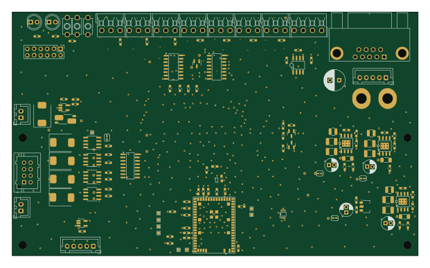
Main ext
roman-khvatov
155 × 93 mm165 parts4LMIT1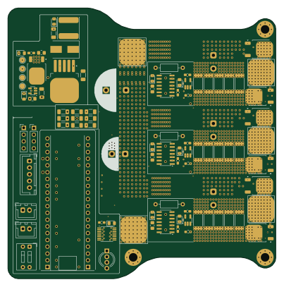 STM32
McQueen
0BitsnBytes
100.5 × 101.5 mm137 parts6LGPL-3.01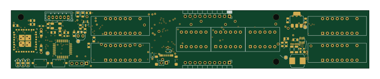 STM32
AstroWeather
jakubprzybytek
185 × 30 mm113 parts6LNo license1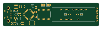 AVR/Arduino
Homegreen-Node
pmalessa
97 × 23.7 mm67 parts2LNo license1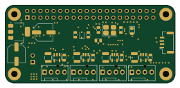 PIC
IOT F26 PROJ
kaballian
65 × 30 mm60 parts4LNo license1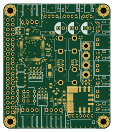 STM32
MainBoard V3 2
banbatakumi
56 × 65 mm145 parts2LNo license0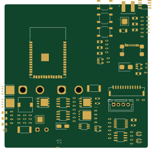 ESP32
Vaporizer
itspolly
73.8 × 73.9 mm108 parts2LUnlicense0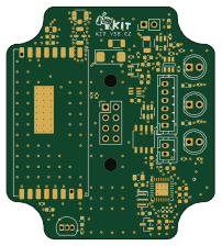 AVR/Arduino
169 node
vsb-fei-440
50 × 55.9 mm65 parts4LMIT0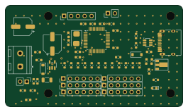 RISC-V
UsbServoController
ucandevices
66 × 38 mm59 parts2LMIT0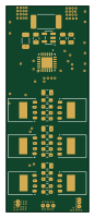
PiESC
CoPYGolF97
20 × 50 mm28 parts4LNo license0- schematic only · 60 parts
Ego coil
wardnb
60 partsCERN-OHL-P-2.00 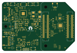 RP2040/RP2350
GMM-7550 USB3 Adapter
75 × 50 mm198 parts4LNo license36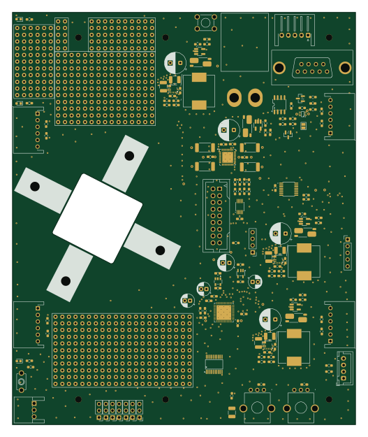 FPGA
Robot
130 × 156 mm161 parts2LMIT1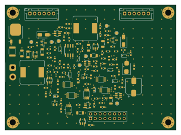
Atlas dock charger
md-sazzad-eee
90 × 66 mm119 parts2LNo license0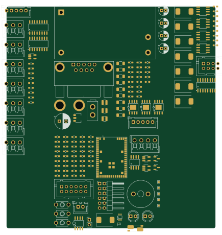
Generic
108.2 × 114.7 mm154 parts2LMIT1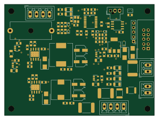 STM32
Psu
kajusK
81 × 60 mm103 parts2LNo license0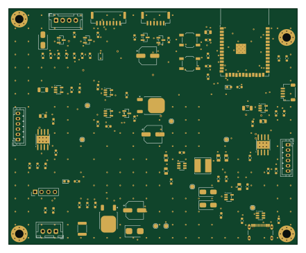 ESP32
Atlas agent ctrl
110 × 90 mm100 parts2LNo license0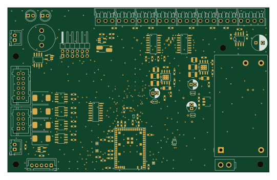
Main int
135 × 85 mm151 parts4LMIT1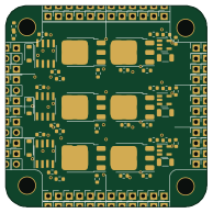
Eddie bldc
ethanjamesauto
48.3 × 48.3 mm63 parts2LNo license1
How designs wire the INA180A2
Read from the KiCad layouts of 18 open source designs, one per repository: what each pin of the INA180A2 connects to, and the resistors, capacitors and other passives placed on it.
- The V+ pin has a decoupling capacitor on 15 of 18 designs, most often 100 nF (then 4.7 µF).
- The OUT pin has a series resistor on 10 of 18 designs, most often 1 kΩ (then 10 kΩ).
- The + pin has a series resistor on 9 of 18 designs, most often 100 mΩ (then 10 mΩ).
- The - pin has a series resistor on 9 of 18 designs, most often 10 kΩ (then 4.7 kΩ).
| Pin | Connected to | Parts on the pin |
|---|---|---|
| OUTpin 1 | Connected to: The microcontroller 33% |
|
| GNDpin 2 | Connected to: GND 94% | — |
| +pin 3 | Connected to: Signal 67% · 12V 22% |
|
| -pin 4 | Connected to: A connector 28% · GND 17% · VCC 22% |
|
| V+pin 5 | Connected to: 3.3V 78% · a signal 22% |
|
Connections count pins, parts count designs; values in brackets are how many parts had that value. Designs read include Power Board by ZhuYanzhen1, Gmm by GMM-7550, PCB-reflow solder table by DerSpatz and SAO Demo Controller by ageppert.
The INA180A2 in open source designs
The gallery holds 24 open source boards using the INA180A2 from 19 GitHub repositories; a typical one measures about 81 × 63.9 mm and carries around 102 components.
61% are two-layer designs, the rest use four layers or more, and 50% carry an open source license.
The most starred is Power Board by ZhuYanzhen1.
Parts used alongside the INA180A2
Microcontrollers on boards using the INA180A2
What boards using the INA180A2 are built for
INA180A2: common questions
Where can I find a INA180A2 reference design?
Each of the 24 boards on this page is a real design using the INA180A2. Open one to see how it is wired up, with the full BOM, a render of the layout and links to its KiCad files.
What decoupling capacitors do designs use on the INA180A2 V+ pin?
The V+ pin has a decoupling capacitor on 15 of 18 designs, most often 100 nF (then 4.7 µF). Counted from the KiCad layouts of 18 open source designs using the INA180A2.
What resistor goes on the INA180A2 OUT pin?
The OUT pin has a series resistor on 10 of 18 designs, most often 1 kΩ (then 10 kΩ). Counted from the KiCad layouts of 18 open source designs using the INA180A2.
What resistor goes on the INA180A2 + pin?
The + pin has a series resistor on 9 of 18 designs, most often 100 mΩ (then 10 mΩ). Counted from the KiCad layouts of 18 open source designs using the INA180A2.
Which microcontrollers do boards using the INA180A2 use?
Most are built on STM32 (6), ESP32 (2), RP2040/RP2350 (2) and AVR/Arduino (2).
How big is a typical board using the INA180A2?
The median is 81 × 63.9 mm, and 61% are two-layer designs.
What is the most popular open source board using the INA180A2?
By GitHub stars, Power Board by ZhuYanzhen1, with 57 stars.
Can I simulate one of these boards using the INA180A2 before building it?
Yes. HardLabs turns a board's netlist and BOM into a working simulation, so you can boot and test firmware against it with no hardware on your desk.