
59 open source boards using the TPS63001DRCR
Real designs built with the TPS63001DRCR, from public GitHub projects: a quick way to see how others power, decouple and connect it. Each board comes with its KiCad files, full parts list and a render — and you can simulate its firmware on HardLabs.
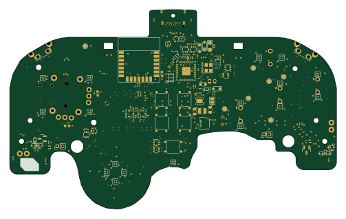 RP2040/RP2350
GC Ultimate Main Board R5
HandHeldLegend
125.7 × 76.6 mm140 parts4LCC-BY-NC-4.061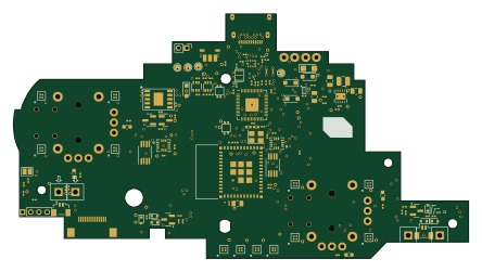 RP2040/RP2350
Progcc 3.2 main
110.9 × 59.8 mm128 parts4LNo license6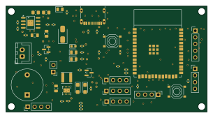 ESP32
Ultrasonic-Whack-A-Mole
TheWasian
76 × 40 mm48 parts4LMIT2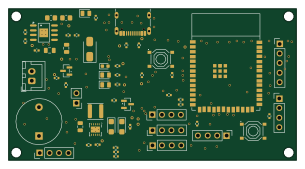 ESP32
Group5-ENGG3000
76 × 40 mm48 parts4LMIT2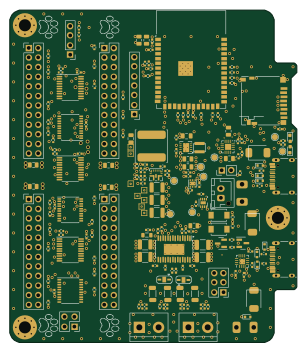 ESP32
Hoerbaer
drachosaurus
76 × 88 mm195 parts4LNo license1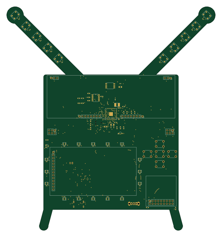 RP2040/RP2350
Defcon sstv badge
livitup
185.7 × 199 mm135 parts4LMIT1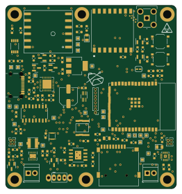 ESP32
Kuhglocke GS
Queens-Rocket-Engineering-Team
65 × 70 mm115 parts2LNo license1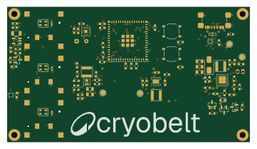 ESP32
Cryobelt
michael201110
90 × 50 mm92 parts4LNo license1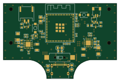 ESP32
Roadster course
jeffreydthompson
60 × 40 mm79 parts4LCC-BY-4.01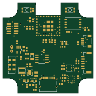 ESP32
KiCAD converted
sai-ydev
47 × 47 mm62 parts4LMIT1 Nordic nRF
Vr trackers
1vers1on
30 × 30 mm61 parts4LNo license1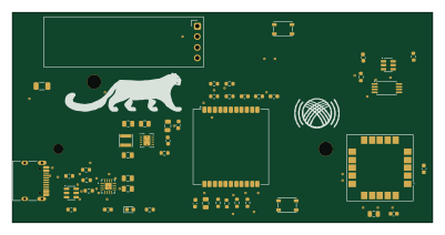
Custom meshtastic node
kyrg4z
100 × 50 mm50 parts2LNo license1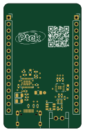
ESP32-Lipo-Powersupply
pierretek
29.7 × 47.6 mm35 parts2LNo license1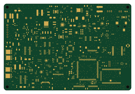 STM32
Mdx1
pingpongshow
135 × 92 mm306 parts4LCC-BY-NC-4.00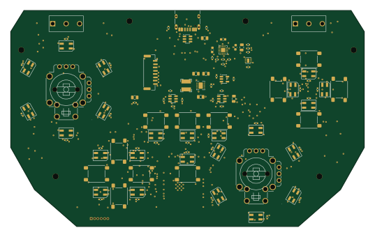 ESP32
Kestrel controller
AthArvA-188
134 × 82 mm182 parts4LNo license0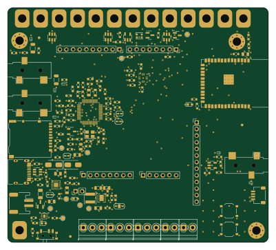 ESP32
Opentouch s3
JoeMighty
100 × 90 mm145 parts4LCustom license0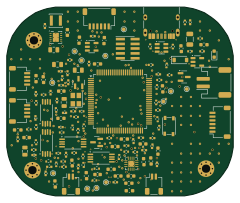 STM32
ANC Helmet - main board (left earcup)
baba2712
60 × 50 mm139 parts4LMIT0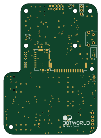 ESP32
Music system
mkno04
50 × 70 mm109 parts2LNo license0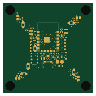 ESP32
FC ESP32
PNT2110
79.8 × 79.8 mm72 parts2LNo license0 ESP32
BardAssistant
jaylingelbach
80 × 60 mm68 parts4LNo license0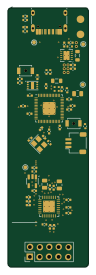 RP2040/RP2350
EnvOpenAudio
Envious-Data
21.3 × 68.7 mm62 parts2LGPL-3.00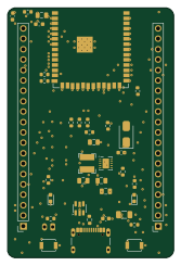 ESP32
Matrix6
FaBoAI
40.6 × 61 mm48 parts2LNo license0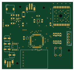 STM32
Senior-Design-Dog-Collar
dmanojlovic
64.8 × 61 mm48 parts2LNo license0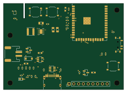 ESP32
Weatherframe
amselgesang
64 × 46 mm46 parts2LMIT0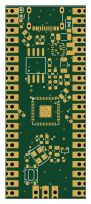 RP2040/RP2350
RPi Pico-V1
TomasD-git
21 × 51 mm45 parts4LMIT0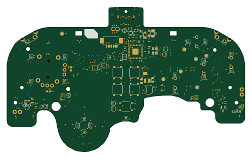 RP2040/RP2350
UGC Main S1
125.7 × 76.6 mm121 parts4LCC-BY-NC-4.061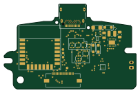
PGC USB+W Module
50.8 × 32.7 mm40 parts4LNo license15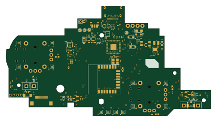 RP2040/RP2350
Progcc 3.3 main
110.9 × 59.8 mm117 parts4LNo license6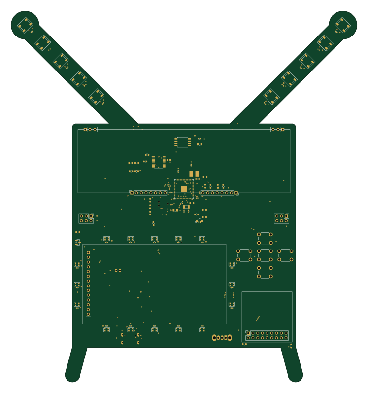 RP2040/RP2350
Defcon sstv badge.backup
185.7 × 199 mm135 parts4LMIT1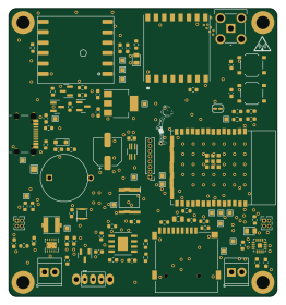 ESP32
Handheld GS
65 × 70 mm99 parts2LNo license1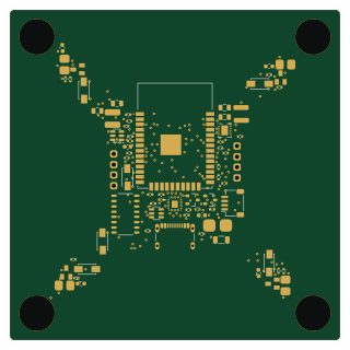 ESP32
Before candidate promotion
79.8 × 79.8 mm72 parts2LNo license0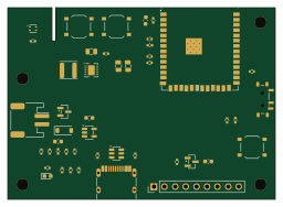 ESP32
Weatherframe placed
64 × 46 mm46 parts2LMIT0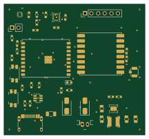 RP2040/RP2350
Sensor node
mohan-bee
54 × 50 mm44 parts2LNo license0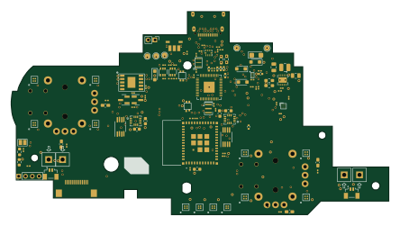 RP2040/RP2350
Procon gcc main
110.9 × 59.8 mm113 parts4LNo license6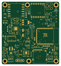 ESP32
Kuhglocke GS
65 × 70 mm115 parts2LNo license3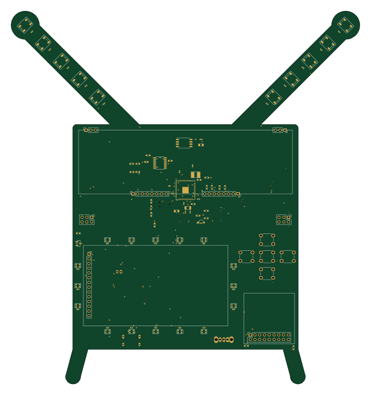 RP2040/RP2350
Defcon sstv badge clean
185.7 × 199 mm135 parts4LMIT1
How designs wire the TPS63001DRCR
Read from the KiCad layouts of 31 open source designs, one per repository: what each pin of the TPS63001DRCR connects to, and the resistors, capacitors and other passives placed on it.
- The L2 pin has a inductor on 31 of 31 designs, most often 2.2 µH (then 1.5 µH).
- The L1 pin has a inductor on 31 of 31 designs, most often 2.2 µH (then 1.5 µH).
- The VINA pin has a capacitor to GND on 31 of 31 designs, most often 100 nF (then 10 µF).
- The VIN pin has a decoupling capacitor on 30 of 31 designs, most often 10 µF (then 100 nF).
| Pin | Connected to | Parts on the pin |
|---|---|---|
| VOUTpin 1 | Connected to: 3.3V 84% · a signal 16% |
|
| L2pin 2 | Connected to: Signal 97% |
|
| PGNDpin 3, 11 | Connected to: GND 100% | — |
| L1pin 4 | Connected to: Signal 97% |
|
| VINpin 5 | Connected to: VSYS 71% · a signal 29% |
|
| ENpin 6 | Connected to: Signal 74% · VSYS 26% |
|
| PS/SYNCpin 7 | Connected to: Signal 68% · GND 19% |
|
| VINApin 8 | Connected to: Signal 68% · VSYS 32% |
|
| GNDpin 9 | Connected to: GND 100% | — |
| FBpin 10 | Connected to: 3.3V 84% · a signal 16% | — |
Connections count pins, parts count designs; values in brackets are how many parts had that value. Designs read include GC Ultimate Main Board R5 by HandHeldLegend, PGC USB+W Module by HandHeldLegend, Procon gcc main pcb by HandHeldLegend and Kuhglocke GS by Queens-Rocket-Engineering-Team.
The TPS63001DRCR in open source designs
The gallery holds 59 open source boards using the TPS63001DRCR from 31 GitHub repositories; a typical one measures about 79.8 × 65 mm and carries around 82 components.
54% use four copper layers or more, and 36% carry an open source license.
The most starred is GC Ultimate Main Board R5 by HandHeldLegend.
Parts used alongside the TPS63001DRCR
Microcontrollers on boards using the TPS63001DRCR
What boards using the TPS63001DRCR are built for
TPS63001DRCR: common questions
Where can I find a TPS63001DRCR reference design?
Each of the 59 boards on this page is a real design using the TPS63001DRCR. Open one to see how it is wired up, with the full BOM, a render of the layout and links to its KiCad files.
How is the TPS63001DRCR L2 pin connected?
The L2 pin has a inductor on 31 of 31 designs, most often 2.2 µH (then 1.5 µH). Counted from the KiCad layouts of 31 open source designs using the TPS63001DRCR.
How is the TPS63001DRCR L1 pin connected?
The L1 pin has a inductor on 31 of 31 designs, most often 2.2 µH (then 1.5 µH). Counted from the KiCad layouts of 31 open source designs using the TPS63001DRCR.
How is the TPS63001DRCR VINA pin connected?
The VINA pin has a capacitor to GND on 31 of 31 designs, most often 100 nF (then 10 µF). Counted from the KiCad layouts of 31 open source designs using the TPS63001DRCR.
What parts are used alongside the TPS63001DRCR?
The USBLC6-2SC6, MCP73831T-2ACI/OT, MAX17048G+T10, BQ24074RGTR and LM66100DCKR appear in the most repositories here.
Which microcontrollers do boards using the TPS63001DRCR use?
Most are built on ESP32 (30), RP2040/RP2350 (21), STM32 (3) and Nordic nRF (1).
How big is a typical board using the TPS63001DRCR?
The median is 79.8 × 65 mm, and 46% are two-layer designs.
What is the most popular open source board using the TPS63001DRCR?
By GitHub stars, GC Ultimate Main Board R5 by HandHeldLegend, with 61 stars.
Can I simulate one of these boards using the TPS63001DRCR before building it?
Yes. HardLabs turns a board's netlist and BOM into a working simulation, so you can boot and test firmware against it with no hardware on your desk.